

Contacts .
9.1. The concept of types of products and design documents
Product call any item or set of items of production to be manufactured at the enterprise.
GOST 2.101-88* establishes the following types of products:
- Details;
- Assembly units;
- Complexes;
- Kits.
When studying the Engineering Graphics course, two types of products are offered for consideration: parts and assembly units.
Detail– a product made from a material that is uniform in name and brand, without the use of assembly operations.
For example: a bushing, a cast body, a rubber cuff (unreinforced), a piece of cable or wire of a given length. Parts also include products that have been coated (protective or decorative), or manufactured using local welding, soldering, and gluing. For example: a body covered with enamel; chrome-plated steel screw; a box glued together from one sheet of cardboard, etc.
Assembly unit- a product consisting of two or more component parts connected to each other at the manufacturing plant by assembly operations (screwing, welding, soldering, riveting, flaring, gluing, etc.).
For example: machine tool, gearbox, welded body, etc.
Complexes- two or more specified products not connected at the manufacturing plant by assembly operations, but intended to perform interrelated operational functions, for example, an automatic telephone exchange, an anti-aircraft complex, etc.
Kits- two or more specified products that are not connected at the manufacturer by assembly operations and represent a set of products that have a general operational purpose of an auxiliary nature, for example, a set of spare parts, a set of tools and accessories, a set of measuring equipment, etc.
The production of any product begins with the development of design documentation. Based on the technical specifications, the design organization develops preliminary design, containing the necessary drawings of the future product, an explanatory note, conducts an analysis of the novelty of the product, taking into account the technical capabilities of the enterprise and the economic feasibility of its implementation.
The preliminary design serves as the basis for the development of working design documentation. A complete set of design documentation determines the composition of the product, its structure, the interaction of its components, the design and material of all its parts and other data necessary for the assembly, manufacture and control of the product as a whole.
Assembly drawing– a document containing an image of an assembly unit and the data necessary for its assembly and control.
General drawing– a document defining the design of a product, the interaction of its components and the principle of operation of the product.
Specification– a document defining the composition of the assembly unit.
The general drawing has the assembly unit number and SB code.
For example: assembly unit code (Figure 9.1) TM.0004ХХ.100 SB the same number, but without a code, has a specification (Figure 9.2) of this assembly unit. Each product included in the assembly unit has its own position number indicated on the general view drawing. By the position number in the drawing you can find in the specification the name, designation of this part, as well as the quantity. In addition, the note may indicate the material from which the part is made.
9.2. Sequence of execution of drawings of parts
Part drawing is a document containing an image of a part and other data necessary for its manufacture and control.
Before completing the drawing, it is necessary to find out the purpose of the part, design features, and find mating surfaces. On the training drawing of the part, it is enough to show the image, dimensions and grade of material.
When drawing a part, the following sequence is recommended:
- Select the main image (see section 2).
- Set the number of images - views, sections, sections, extensions that clearly give an idea of the shape and size of the part, and supplement the main image with any information, remembering that the number of images in the drawing should be minimal and sufficient.
- Select the image scale according to GOST 2.302-68. For images on working drawings, the preferred scale is 1:1. The scale in the part drawing does not always have to match the scale of the assembly drawing. Large and simple details can be drawn on a reduction scale (1:2; 1:2.5; 1:4; 1:5, etc.), small elements are best depicted on an enlargement scale (2:1; 2.5 :1; 4:1; 5:1; 10:1; etc.).
- Select drawing format. The format is selected depending on the size of the part, number and scale of images. Images and inscriptions should occupy approximately 2/3 of the working area of the format. The working field of the format is limited by a frame in strict accordance with GOST 2.301-68* for the design of drawings. The main inscription is located in the lower right corner (on A4 format the main inscription is located only along the short side of the sheet);
- Layout the drawing. To rationally fill out the format field, it is recommended to outline the overall rectangles of the selected images with thin lines, then draw the axes of symmetry. The distances between the images and the format frame should be approximately the same. It is selected taking into account the subsequent application of extension, dimension lines and corresponding inscriptions.
- Draw the detail. Apply extension and dimension lines in accordance with GOST 2.307-68. After drawing the part with thin lines, remove the extra lines. Having chosen the thickness of the main line, trace the images, observing the ratios of the lines in accordance with GOST 3.303-68. The outline must be clear. After tracing, complete the necessary inscriptions and put down the numerical values of the dimensions above the dimension lines (preferably font size 5 according to GOST 2.304-68).
- Fill out the title block. In this case, indicate: the name of the part (assembly unit), the material of the part, its code and number, who and when the drawing was made, etc. (Figure 9.1)
Stiffening ribs and spokes are shown unshaded in longitudinal sections.
9.3. Applying dimensions
Dimensioning is the most critical part of working on a drawing, since incorrectly placed and extra dimensions lead to defects, and lack of dimensions causes production delays. Below are some recommendations for applying dimensions when drawing parts.
The dimensions of the part are measured using a meter on the drawing of the general view of the assembly unit, taking into account the scale of the drawing (with an accuracy of 0.5 mm). When measuring the largest thread diameter, it is necessary to round it to the nearest standard, taken from the reference book. For example, if the diameter of a metric thread is measured to be d = 5.5 mm, then it is necessary to accept an M6 thread (GOST 8878-75).
9.3.1. Size classification
All sizes are divided into two groups: basic (conjugate) and free.
Main Dimensions
are included in the dimensional chains and determine the relative position of the part in the assembly, they must ensure:
- location of the part in the assembly;
- precision of interaction of assembled parts;
- assembly and disassembly of the product;
- interchangeability of parts.
An example is the dimensions of the female and male elements of mating parts (Figure 9.2). The common contacting surfaces of the two parts have the same nominal size.
Parts are not included in the dimensional chains. These dimensions determine those surfaces of the part that do not connect with the surfaces of other parts, and therefore they are made with less accuracy (Figure 9.2). 
A– covering surface; B– covered surface;
IN- free surface; d– nominal size
Figure 9.2
9.3.2. Dimensioning methods
The following sizing methods are used:
- chain;
- coordinate;
- combined.
At chain
method (Figure 9.3), the dimensions are entered sequentially one after another. With this sizing, each roller step is processed independently, and the technological base has its own position. At the same time, the accuracy of the size of each element of the part is not affected by errors in the execution of previous dimensions. However, the total size error consists of the sum of the errors of all sizes. Drawing dimensions in the form of a closed chain is not permitted, except in cases where one of the dimensions of the chain is indicated as a reference. Reference dimensions in the drawing are marked * and written in the field: "* Dimensions for reference"(Figure 9.4). 
Figure 9.3 
Figure 9.4
At coordinate method, dimensions are set from the selected bases (Figure 9.5). With this method, there is no summation of sizes and errors in the location of any element relative to one base, which is its advantage. 
Figure 9.5
Combined The dimensioning method is a combination of chain and coordinate methods (Figure 9.6). It is used when high precision is required in the manufacture of individual elements of a part.

Figure 9.6
According to their purpose, dimensions are divided into overall, connecting, installation and structural.
Dimensional dimensions determine the maximum external (or internal) contours of the product. They are not always applied, but are often listed for reference, especially for large cast parts. The overall dimensions are not applied to bolts and studs.
Connection And installation Dimensions determine the size of the elements by which this product is installed at the installation site or connected to another. These dimensions include: the height of the center of the bearing from the plane of the base; distance between hole centers; diameter of the circle of centers (Figure 9.7).
A group of dimensions that determine the geometry of individual elements of a part intended to perform a particular function, and a group of dimensions for elements of a part, such as chamfers, grooves (the presence of which is caused by processing or assembly technology), are performed with varying accuracy, therefore their dimensions are not included in one dimensional chain (Figure 9.8, a, b).
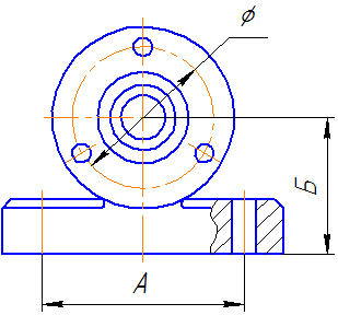
Figure 9.7
Figure 9.8, a
Figure 9.8, b
9.4. Making a drawing of a part that has the shape of a body of rotation
Parts that have the shape of a body of rotation are found in the vast majority (50-55% of the original parts) in mechanical engineering, because rotational movement is the most common type of movement of elements of existing mechanisms. In addition, such parts are technologically advanced. These include shafts, bushings, disks, etc. processing of such parts is carried out on lathes, where the axis of rotation is located horizontally.
Therefore, parts having the shape of a body of rotation are placed on the drawings so that the axis of rotation was parallel to the title block of the drawing(stamp). It is advisable to place the end of the part, taken as the technological base for processing, on the right, i.e. the way it will be positioned during processing on the machine. The working drawing of the bushing (Figure 9.9) shows the execution of a part that is a surface of rotation. The outer and inner surfaces of the part are limited by surfaces of rotation and planes. Another example could be the “Shaft” part (Figure 9.10), limited by coaxial surfaces of rotation. The center line is parallel to the title block. Dimensions are given in a combined way.

Figure 9.9 - Working drawing of a part of the surface of rotation 
Figure 9.10 — Working drawing of the “Shaft” part
9.5. Making a drawing of a part made from sheet metal
This type of parts includes gaskets, covers, strips, wedges, plates, etc. Parts of this shape are processed in various ways (stamping, milling, planing, cutting with scissors). Flat parts made of sheet material are usually depicted in one projection, defining the contour of the part (Figure 9.11). The thickness of the material is indicated in the title block, but it is recommended to indicate it again on the image of the part, on the drawing - s3. If the part is bent, then a development is often shown in the drawing. 
Figure 9.11 - Drawing of a flat part
9.6. Execution of a drawing of a part manufactured by casting, followed by machining
Molding by casting allows you to obtain a fairly complex shape of a part, with virtually no loss of material. But after casting, the surface turns out to be quite rough, therefore, the working surfaces require additional mechanical processing.
Thus, we get two groups of surfaces - casting (black) and processed after casting (clean).
The casting process: molten material is poured into the casting mold, after cooling the workpiece is removed from the mold, for which most of the surfaces of the workpiece have casting slopes, and the mating surfaces have casting rounding radii.
Casting slopes need not be depicted, but casting radii must be depicted. The dimensions of the casting radii of roundings are indicated in the technical requirements of the drawing by writing, for example: Unspecified casting radii 1.5 mm.
The main feature of applying dimensions: since there are two groups of surfaces, that is, two groups of sizes, one connects all black surfaces, the other connects all clean surfaces, and for each coordinate direction it is allowed to put down only one size, connecting these two groups of sizes.
In Figure 9.12, these dimensions are: in the main image - size of the cover height - 70, in the top view - size 10 (from the lower end of the part) (highlighted in blue).
When casting, a casting material is used (letter L in the designation), which has increased fluidity, for example:
- steel according to GOST 977-88 (Steel 15L GOST 977-88)
- gray cast iron according to GOST 1412-85 (SCh 15 GOST 1412-85)
- casting brass according to GOST 17711-93 (LTs40Mts1.5 GOST 17711-93)
- aluminum alloys according to GOST 2685-75 (AL2 GOST 2685-75)

Figure 9.12 - Drawing of a casting part
9.7. Drawing a spring
Springs are used to create certain forces in a given direction. According to the type of loading, springs are divided into compression, tension, torsion and bending springs; in shape - for screw cylindrical and conical, spiral, sheet, disc, etc. rules for the execution of drawings of various springs are established by GOST 2.401-68. In the drawings, springs are drawn conventionally. The coils of a helical cylindrical or conical spring are depicted by straight lines tangent to sections of the contour. It is allowed to depict only sections of turns in a section. Springs are shown with right-hand winding, with the true direction of the coils indicated in the technical requirements. An example of a training drawing of a spring is shown in Figure 9.13.
To obtain flat bearing surfaces on the spring, the outer coils of the spring are pressed to? turn or a whole turn and grind. The pressed turns are not considered working, therefore the total number of turns n is equal to the number of working turns plus 1.5?2:n 1 =n+(1.5?2) (Figure 9.14).
The construction begins by drawing axial lines passing through the centers of the sections of the spring coils (Figure 9.15, a). Then a circle is drawn on the left side of the center line, the diameter of which is equal to the diameter of the wire from which the spring is made. The circle touches the horizontal line on which the spring rests. Then you need to draw a semicircle from the center located at the intersection of the right axis with the same horizontal line. To construct each subsequent coil of the spring, sections of the coils are constructed on the left at a step distance. On the right, each section of the coil will be located opposite the middle of the distance between the coils built on the left. By drawing tangents to the circles, a cross-sectional image of the spring is obtained, i.e. image of the coils lying behind the plane passing through the axis of the spring. To depict the front halves of the turns, tangents to the circles are also drawn, but with a rise to the right (Figure 9.15, b). The front quarter of the support turn is constructed so that the tangent to the semicircle simultaneously touches the left circle in the lower part. If the wire diameter is 2 mm or less, then the spring is depicted by lines 0.5–1.4 mm thick. When drawing helical springs with a number of turns of more than four, show one or two turns at each end, in addition to the support ones, drawing axial lines through the centers of the sections of the turns along the entire length. In working drawings, helical springs are depicted so that the axis has a horizontal position.
As a rule, a test diagram showing the dependence of deformations (tension, compression) on the load (P 1; P 2; P 3), where H 1 is the height of the spring at preliminary deformation P 1, is placed in the working drawing; N 2 - the same, with working deformation P 2; H 3 – height of the spring at maximum deformation P 3; H 0 – height of the spring in working condition. In addition, under the image of the spring indicate:
- Spring standard number;
- Winding direction;
- n – number of working turns;
- Total number of turns n;
- Length of the deployed spring L=3.2?D 0 ?n 1 ;
- Dimensions for reference;
- Other technical requirements.
On training drawings, it is recommended to indicate paragraphs from the listed points. 2,3,4,6. The execution of the test diagram is also not provided for when completing the training drawing. 
 |
|
| A | b |

9.8. Making a gear drawing
A gear is an important component of many designs of devices and mechanisms designed to transmit or transform motion.
The main elements of a gear wheel: hub, disk, ring gear (Figure 9.16). 
The tooth profiles are normalized by the relevant standards.
The main parameters of the gear are (Figure 9.17):
m=Pt/ ? [mm] – module;
da= mst(Z+2) – diameter of the circle of the tooth tips;
d= mst Z– pitch diameter;
df= mst (Z– 2.5) – diameter of the circle of the depressions;
St= 0.5 mst? – tooth width;
h a– height of the tooth head;
h f– height of the tooth stem;
h = h a +h f– tooth height;
P t– dividing circumferential step. 
The main characteristic of the ring gear is the modulus - a coefficient connecting the circumferential pitch with the number ?. The module is standardized (GOST 9563-80).
m = Pt/ ? [mm]
| 0,25 | (0,7) | (1,75) | 3 | (5,5) | 10 | (18) | 32 |
| 0,3 | 0,8; (0,9) | 2 | (3,5) | 6 | (11) | 20 | (36) |
| 0,4 | 1; (1,125) | (2,25) | 4 | (7) | 12 | (22) | 40 |
| 0,5 | 1,25 | 2,5 | (4,5) | 8 | (14) | 25 | (45) |
| 0,6 | 1,5 | (2,75) | 5 | (9) | 16 | (28) | 50 |
On training drawings of gears:
Tooth head height – h a = m;
Tooth stem height – h f = 1.25m;
Roughness of tooth working surfaces – Ra 0.8[µm];
At the top right of the sheet, a table of parameters is drawn up, the dimensions of which are shown in Figure 9.18; often only the modulus value, the number of teeth and the pitch diameter are filled in. 
Figure 9.18 — Parameter table
Wheel teeth are depicted conventionally, according to GOST 2.402-68 (Figure 9.19). The dashed line is the dividing circle of the wheel.
In the section the tooth is shown uncut.
Figure 9.19 - Image of a gear wheel a - in section, b - in front view and c - in left view
The roughness on the lateral working surface of the tooth in the drawing is indicated on the pitch circle.
An example of a gear drawing is shown in Figure 9.20. 
Figure 9.20 — An example of a training drawing of a gear
9.9. Sequence of reading a general view drawing
- Using the data contained in the title block and the description of the product’s operation, find out the name, purpose and operating principle of the assembly unit.
- Based on the specification, determine which assembly units, original and standard products the proposed product consists of. Find in the drawing the number of parts indicated in the specification.
- Based on the drawing, represent the geometric shape, the relative position of the parts, how they are connected and the possibility of relative movement, that is, how the product works. To do this, it is necessary to consider in the drawing of the general view of the assembly unit all the images of this part: additional views, sections, sections, and extensions.
- Determine the sequence of assembly and disassembly of the product.
When reading a general view drawing, it is necessary to take into account some simplifications and conventional images in the drawings, allowed by GOST 2.109-73 and GOST 2.305-68*:
It is allowed not to show on the general view drawing:
- chamfers, roundings, grooves, recesses, protrusions and other small elements (Figure 9.21);
- gaps between the rod and the hole (Figure 9.21);
- covers, shields, casings, partitions, etc. in this case, an appropriate inscription is made above the image, for example: “The cover pos. 3 is not shown”;
- inscriptions on plates, scales, etc. depict only the contours of these parts;
- in a cross-section of an assembly unit, different metal parts have opposite hatching directions, or different hatching densities (Figure 9.21). It must be remembered that for the same part, the density and direction of all hatchings are the same in all projections;
- on sections they are shown uncut:
- components of the product for which independent assembly drawings are drawn up;
- such parts as axles, shafts, fingers, bolts, screws, studs, rivets, handles, as well as balls, keys, washers, nuts (Figure 9.21);
- a welded, soldered, glued product made of a homogeneous material assembled with other products in the section has shading in one direction, while the boundaries between the parts of the product are shown as solid lines;
- It is allowed to show evenly spaced identical elements (bolts, screws, holes); not all of them are shown, one is enough;
- if not a single hole or connection falls into the cutting plane, then it is allowed to “rotate” it so that it falls into the cut image.
Assembly drawings contain reference, installation, and as-built dimensions. Executive dimensions are dimensions for those elements that appear during the assembly process (for example, pin holes). 

9.10. Rules for filling out the specification
The specification for training assembly drawings typically includes the following sections:
- Documentation;
- Complexes;
- Assembly units;
- Details;
- Standard products;
- Other products;
- Materials;
- Kits.
The name of each section is indicated in the “Name” column, underlined with a thin line and highlighted with empty lines.
- In the “Documentation” section, design documents for the assembly unit are entered. “Assembly drawing” is entered into this section in training drawings.
- The sections “Assembly units” and “Parts” include those components of the assembly unit that are directly included in it. In each of these sections, the components are written by their name.
- The “Standard Products” section records products used in accordance with state, industry or republican standards. Within each category of standards, records are made in homogeneous groups, within each group - in alphabetical order of product names, within each name - in ascending order of standard designations, and within each standard designation - in ascending order of the main parameters or dimensions of the product.
- The “Materials” section includes all materials directly included in the assembly unit. Materials are recorded by type and in the sequence specified in GOST 2.108 - 68. Within each type, materials are recorded in alphabetical order of names of materials, and within each name - in ascending order of size and other parameters.
In the “Quantity” column indicate the number of components per one specified product, and in the “Materials” section - the total quantity of materials per one specified product indicating the units of measurement - (for example, 0.2 kg). Units of measurement may be written in the “Note” column.
How to create a specification in the KOMPAS-3D program is described in the corresponding topic Laboratory work!
For questions regarding tutoring in engineering graphics (drawing), you can contact us in any way convenient for you in the section Contacts . Full-time and distance learning via Skype is possible: RUB 1,000/academic hour.
GOST 2.052-2006
Unified system of design documentation
ELECTRONIC PRODUCT MODEL
General provisions
Unified system for design documentation. Electronic model of product. General principles
Date of introduction - 2006-09-01
Preface
The goals, basic principles and basic procedure for carrying out work on interstate standardization are established by GOST 1.0-92 “Interstate standardization system. Basic provisions" and GOST 1.2-97 "Interstate standardization system. Interstate standards, rules and recommendations for interstate standardization. Procedure for development, adoption, application, updating, cancellation"
1
Application area
This standard establishes general requirements for the implementation of electronic models of products (parts, assembly units) of mechanical engineering and instrument making.
Based on this standard, it is possible, if necessary, to develop standards that take into account the specific features of the implementation of electronic models for products of specific types of equipment, depending on their specifics.
GOST 2.051-2006 Unified system of design documentation. Electronic documents. General provisions
GOST 2.101-68 Unified system of design documentation. Types of products
GOST 2.102-68 Unified system of design documentation. Types and completeness of design documents
GOST 2.104-2006 Unified system of design documentation. Basic inscriptions
GOST 2.109-73 Unified system of design documentation. Basic requirements for drawings
GOST 2.305-68 Unified system of design documentation. Images - views, sections, sections
GOST 2.307-68 Unified system of design documentation. Drawing dimensions and maximum deviations
GOST 2.317-69 Unified system of design documentation. Axonometric projections
Note - When using this standard, it is advisable to check the validity of the reference standards using the “National Standards” index compiled as of January 1 of the current year, and according to the corresponding information indexes published in the current year. If the reference standard is replaced (changed), then when using this standard you should be guided by the replaced (changed) standard. If the reference standard is canceled without replacement, then the provision in which a reference is made to it is applied in the part that does not affect this reference.
3 Terms, definitions and abbreviations
3.1 Terms and Definitions
The following terms with corresponding definitions are used in this standard:
3.1.1 electronic product model(model): Electronic model of a part or assembly unit in accordance with GOST 2.102.
3.1.2 electronic geometric model (geometric model): An electronic model of a product that describes the geometric shape, dimensions and other properties of the product, depending on its shape and size.
3.1.3 geometric element: The identified (named) geometric object used in the dataset.
Note - A geometric object can be a point, line, plane, surface, geometric figure, geometric body.
3.1.4 model geometry: A set of geometric elements that are elements of the geometric model of a product.
3.1.5 auxiliary geometry: A set of geometric elements that are used in the process of creating a geometric model of a product, but are not elements of this model.
Note - Geometric elements can be a center line, spline reference points, guides and forming surface lines, etc.
3.1.6 model attribute: Dimension, tolerance, text or symbol required to define the geometry of a product or its characteristics* 1) .
3.1.7 model space: The space in the model coordinate system in which the geometric model of the product is executed.
3.1.8 plane of symbols and instructions: A plane in the model space on which visually perceptible information is displayed, containing the values of model attributes, technical requirements, symbols and instructions.
3.1.9 location data: Data that determines the placement and orientation of the product and its components in the model space in the specified coordinate system.
3.1.10 solid state model: A three-dimensional electronic geometric model that represents the shape of a product as a result of the composition of a given set of geometric elements using Boolean algebra operations to these geometric elements.
3.1.11 surface model: A three-dimensional electronic geometric model, represented by a set of limited surfaces that determine the shape of the product in space.
3.1.12 frame model: A three-dimensional electronic geometric model, represented by a spatial composition of points, segments and curves that determine the shape of the product in space.
3.1.13 component of the product: A product of any type in accordance with GOST 2.101, included in the product and considered as a single whole.
3.1.14 model file: A file containing information about geometric elements, attributes, symbols, and indications that are considered as a whole*.
3.1.15 electronic layout: An electronic model of a product that describes its external shape and dimensions, allowing one to fully or partially evaluate its interaction with elements of the production and/or operational environment, which serves for decision-making in the development of the product and the processes of its manufacture and use.
3.2 Abbreviations
The following abbreviations are used in this standard:
POU - plane of designations and instructions;
PZ - explanatory note;
KD - design document;
EMR - electronic model of the product;
EMD - electronic model of the part;
EMSE - electronic model of an assembly unit;
EMK - electronic layout;
CAD - computer-aided design system;
EGM - electronic geometric model.
4 General provisions
4.1 In a computer environment, EMR is presented as a set of data that together determine the geometry of the product and other properties necessary for the manufacture, control, acceptance, assembly, operation, repair and disposal of the product.
4.2 EMR is usually used:
To interpret the entire data set that makes up the model (or part of it) in automated systems;
To visually display the design of a product during design work, production and other operations;
For the production of drawing design documentation in electronic and/or paper form.
4.3 General requirements for the implementation of design documentation in the form of an electronic model of the product - in accordance with GOST 2.051. EMR forms the content part of the corresponding design documentation in accordance with GOST 2.102 (EMD or EMSE). Requirements for the composition and presentation of information in accordance with ISO 10303-1, ISO 10303-11, ISO 10303-42, ISO 10303-201. The requisite part is carried out in accordance with GOST 2.104*.
4.4 EMR, as a rule, consists of a geometric model of the product, an arbitrary number of model attributes, and may include technical requirements. The schematic composition of the model is shown in Figure B.1 (Appendix B).
4.5 The model must contain a full set of design, technological and physical parameters in accordance with GOST 2.109, necessary for performing calculations, mathematical modeling, development of technological processes, etc.
4.6 The completeness and detail of the model at various stages of development must comply with the requirements of the standards of the Unified System of Design Documentation.
4.7 The electronic design document, made in the form of a model, must meet the following basic requirements:
a) attributes (models), designations and instructions given in the model must be necessary and sufficient for the specified purpose of release (for example, manufacturing a product or constructing a drawing in paper and/or electronic form);
b) all size values must be obtained from the model;
c) related geometric elements, attributes, symbols and indications defined in the model must be consistent;
d) attributes, designations and instructions defined and/or specified in the model and shown in the drawing must be consistent*;
e) if the model does not contain all the design data of the product, then this must be indicated*;
f) it is not allowed to provide references to regulatory documents defining the shape and dimensions of structural elements (holes, chamfers, grooves, etc.) if they do not contain a geometric description of these elements. All data for their manufacture must be given in the model;
g) the bit depth when rounding the values of linear and angular dimensions must be specified by the developer;
4.8 When visualizing (displaying) a model on an electronic device (for example, a display screen), the following rules are followed:
a) dimensions, maximum deviations and instructions (including technical requirements) should be shown in the main projection planes in accordance with GOST 2.305, axonometric projections - in accordance with GOST 2.317 or other projection planes convenient for visual perception of the displayed information*;
b) all text (requirements, designations and instructions) must be defined in one or more SOUs;
c) the display of information in any SOU should not overlap with the display of any other information in the same SOU;
d) the text of requirements, designations and instructions within any POU should not be placed on top of the model geometry when it is located perpendicular to the model display plane;
e) for axonometric projections, the orientation of the fender must be parallel, perpendicular or coincident with the surface to which it is applied;
f) when rotating the model, the required reading direction must be ensured in each POU*.
An example of displaying the SOA for different orientations of the model in the model space when visualizing the model on an electronic display device is given in Appendix B.
4.9 When visualizing the model it is allowed:
a) do not present the model in drawing format;
b) do not show the display of central (center) lines or central planes to indicate dimensions;
c) do not show shading in sections and sections;
d) do not present the details of the main inscription and additional columns to it in a drawing format. In this case, viewing the details of the main inscription and additional columns to it should be provided upon request. The composition of the details is in accordance with GOST 2.104;
e) show additional design parameters using auxiliary geometry, for example, the coordinates of the center of mass;
f) show dimensions and maximum deviations without using sections;
g) include links to documents of another type, provided that the reference document is in electronic form. When transferring design documentation to another enterprise, these documents must be included in the product design documentation package*.
4.10 When specifying attributes, the conventions (signs, lines, alphabetic and alphanumeric designations, etc.) established in the standards of the Unified System of Design Documentation are used. The dimensions of symbols are determined taking into account clarity and clarity and are kept the same for repeated use within the same model.*
4.11 When developing the model, the use of electronic libraries (electronic catalogs) of standard and purchased products is provided. The application, methods and rules for using electronic libraries are established by the developer, unless this is specified in the technical specifications or the protocol for reviewing the technical proposal (draft design)*.
For documentation for products developed by order of the Ministry of Defense, the nomenclature and technical content of the electronic product libraries used, as well as the organization’s regulatory documents, must be agreed with the customer (customer’s representative office).
4.12 It is allowed to include references to standards and technical specifications in the model if they fully and unambiguously define the relevant requirements. It is allowed to provide references to technological instructions when the requirements established by these instructions are the only ones that guarantee the required quality of the product.
For documentation for products developed by order of the Ministry of Defense, standards and technological instructions of organizations must be agreed upon with the customer (customer's representative office).
4.13 The model does not include technological instructions. As an exception, it is allowed to include technological instructions in cases provided for by GOST 2.109.
5 General requirements for the implementation of an electronic model of a product
5.1 EMR must contain at least one coordinate system. The coordinate system of the model is depicted by three mutually perpendicular lines with the origin located at the intersection of three axes, in this case:
The positive direction and designation of each axis must be shown;
The model's right-handed coordinate system (Figure 1) should be used unless a different coordinate system is specified.
If necessary, it is allowed to use a non-orthogonal coordinate system of the model.
5.2 When developing EMR, the following types of product shape representation are used in accordance with ISO 10303-42, ISO 10303-41, ISO 10303-43:
Wireframe representation;
Surface presentation;
Solid representation.
The composition and relationship of the types of product form representation are shown in Figure B.2 (Appendix B)*.
5.3 When developing EMR, provide a representation of the model file in accordance with ISO 10303-21, ISO 10303-22.
5.4 In EMR, it is possible to perform a simplified representation of model parts such as holes, threads, tapes, springs, etc., using a partial definition of the model geometry, model attributes, or a combination thereof.
5.5 The initial orientation of the EMR in the model space is not specified.
Figure 1 - Coordinate system of the electronic product model
6 Requirements for types of electronic product models
6.1 Electronic model of the part
6.1.1 EMD is developed, as a rule, for all parts included in the product, if the technical specifications provide for the execution of documentation only in the form of EMD.
6.1.2 EMD, as a rule, should be carried out in the dimensions to which the product must comply before assembly. Exceptions are the cases specified in GOST 2.109. The values of maximum deviations, surface roughness and other necessary values of the attributes of the product or its elements must correspond to the values before assembly.
The maximum deviations and surface roughness of product elements resulting from processing during or after assembly are indicated in the EMSE.
6.1.3 Material symbols are recorded in the EMD in accordance with GOST 2.109.
6.1.4 If the use of material substitutes is envisaged for the manufacture of a part, then they are given in the technical requirements. If EMR is performed taking into account the texture of the material, then the texture of the base material should be specified.
6.1.5 If a part must be made of a material that has a certain direction of fibers, base, etc. (metal tape, fabric, paper, wood) or the arrangement of layers of the part material (textolite, fiber, getinax), then, if necessary, it is allowed to indicate the direction of the grain or the arrangement of layers of material in a part.
6.2 Electronic model of the assembly unit
6.2.1 EMSE must give an idea of the location and mutual connection of the components connected into an assembly unit, and contain the necessary and sufficient information for the assembly and control of the assembly unit.
6.2.3 EMSEs included in a product of a higher hierarchy level are recommended to be included in the model of this product as independent models, placing them in the EMSE coordinate system of a higher hierarchy level and specifying location data.
6.2.4 The organization of the levels of inclusion of components included in the EMSE of the final product must be necessary and sufficient for the rational organization of production (assembly and control) of products.
6.2.5 EMSE must contain parameters and requirements that must be fulfilled or monitored*:
a) position numbers of the components included in the product;
b) installation, connecting and other necessary reference dimensions;
c) technical characteristics of the product (if necessary);
d) instructions on the nature of the mating of EMSE elements and methods for its implementation, if the matching accuracy is ensured not by specified maximum dimensional deviations, but by selection, fitting, etc.;
e) instructions on the implementation of permanent connections (welded, soldered, etc.). In the EMSE of products of a single production, it is allowed to indicate data on the preparation of edges for (permanent connections (welding, soldering, etc.).
6.2.6 It is allowed to include models of boundary (adjacent) products (“environment”) in the EMSE, observing the dimensions that determine their relative position.
Installation and connection dimensions required for connection with other products must be indicated with maximum deviations*.
6.2.7 All components of the assembly unit are numbered. Item numbers must correspond to those specified in the specification and/or electronic structure of the product of this assembly unit*.
6.2.8 It is allowed to carry out documentation for the assembly unit only in the form of EMSE. In this case, the EMSE provides additional data necessary for the manufacture of parts (surface roughness, shape deviations, etc.).
6.2.9 If, when assembling a product for its adjustment, adjustment, compensation, the component parts are selected, then in the EMSE they are included in one (main) of the possible applications that provide nominal parameters.
The technical requirements contain the necessary instructions for installing such “selected” parts. The wording of the instructions is in accordance with GOST 2.109.
6.2.10 If, after assembling the product during its storage and (or) transportation, it is necessary to install protective temporary parts (cover, plug, etc.), these parts are included in the EMSE as they should be installed during storage and transportation. If protective temporary parts during storage and transportation must be installed instead of any devices or mechanisms removed from the product, then their EMD is included in the EMSE, and the relevant instructions are included in the technical requirements*.
6.3 Electronic layout
6.3.1 EMC is a type of EMR (EMSE) and is intended to assess the interaction of the components of a prototype product or the product as a whole with elements of the production and/or operational environment.
6.3.2 EMC is developed at design stages, is not intended for the manufacture of products based on them and, as a rule, does not contain data for manufacturing and assembly.
6.3.3 As a rule, EHR is performed on the basis of EMC using multimedia technologies showing the dynamics of movement and extreme positions of moving, extending or tilting parts, levers, carriages, hinged covers, etc.
6.3.4 EHR should be carried out, as a rule, with simplifications corresponding to the purposes of its development. The detail of the EHR should be sufficient to give a comprehensive idea of the external outlines of the product, the positions of its protruding parts (levers, flywheels, handles, buttons, etc.), and elements that must be constantly in the field of view (for example, scales ), on the location of elements connecting the product with other products.
6.3.5 If necessary, it is allowed to provide data on the operation of the product and the interaction of its parts. This data is entered into the annotation part of the EHR. It is also allowed to place a link to an (electronic) text document (usually a PP).
6.3.6 It is allowed not to show elements that protrude beyond the main contour by an insignificant amount compared to the dimensions of the product.
6.3.7 It is allowed to include in the EMC parts and assembly units that are not part of the product (“furnishings”), observing their relative position.
6.3.8 The accuracy of the construction of the EMC must be necessary and sufficient to determine the overall dimensions of the product, installation and connection dimensions and, if necessary, dimensions determining the position of the protruding parts.
Appendix A
Creating a drawing of a part according to GOST
a) Creating a frontal projection of the part (front view) (Fig. 1)
create a document Drawing;
fill out the title block: Insert/Head block, or double-click in the title block field;
enter in the field Names details – Body, in the field cipher– group number, grade book number separated by a dot, in the field Developed by– Your last name;
activate the panel Geometry, select Rectangle and build a rectangle with axes 50 mm high and 120 mm wide;
select Auxiliary lines/Parallel lines and from the vertical center line create two parallel straight lines at a distance of 25 mm;
similarly create an auxiliary line 12 mm above the horizontal line of the base;
select Continuous Entry of Objects and draw the outline of the part (Fig. 2);

to remove unnecessary segments, activate the panel Editing, select Truncate a curve, also delete the horizontal centerline;
build two pairs of auxiliary lines parallel to the vertical axis at a distance of 8 and 15 mm, also build an auxiliary line parallel to the top contour line and 20 mm below it;
by using Continuous input of objects draw the outline of the central holes;

delete auxiliary lines;
create chamfers: panel Geometry/ chamfers; install Length 1.6 mm, Corner 45 0 (Fig. 4)

complete the missing lines (Fig. 5)

To construct mounting holes, build two auxiliary straight lines at a distance of 45 mm from the center line;
build the mounting holes similarly to the central ones, diameter 8 mm, depth 12 mm, width 1.6 mm, angle 45 0;
apply shading: Geometry/Hatching; style-metal, color black, step - 3 mm, angle - 45 0, use the mouse to indicate the areas that need to be shaded (Fig. 6)

b) Creating a horizontal projection of the part (top view) (Fig. 1)
to create this projection it is necessary to use projection connections; select vertical auxiliary line and draw lines (Fig. 7)

build rectangle height 50 and width 120 mm (with axles);
to show the location of the mounting holes, draw two parallel to the horizontal centerline auxiliary straight at a distance of 12 mm (Fig. 8);

using auxiliary straight, construct a mounting hole from two circles and boss (Fig. 9);

To create flats on the boss parallel to the horizontal centerline, draw two auxiliary straight at a distance of 20 mm, using Segment draw flats and remove unnecessary segments (command Editing/ Truncate a curve) (Fig. 10);
select the mounting hole and use Editing/Symmetry build a hole symmetrical about the horizontal axis;
in the same way, select both mounting holes and build two holes symmetrical about the vertical axis (Fig. 11);
remove unnecessary auxiliary lines;
create central holes (Fig. 12);


c) Preparation of the drawing for use in the production process of manufacturing the part.
enter the required dimensions (Fig. 1);
draw a cut line on the horizontal projection (Fig. 1): activate the panel Designations, press Cut line. Since the cut is complex, use on the panel Properties button Difficult cut.
edit the relative position of size and section designations;
enter the designation of the section on the frontal projection: Symbols/Text. In order for the program to automatically insert a horizontal projection section designation, right-click in the field Text and from the context menu that opens, select Insert link, in the dialog box Link the designation of the created section is displayed and press OK.
install in window Properties to indicate a cut, font size 7;
Place a shape tolerance designation on the frontal projection, which specifies the parallelism of the upper part of the base of the part relative to the bottom: Designations/Base. Fix the position of the base surface designation (Fig. 14);
set the shape tolerance margin: Designations/Form Tolerance(Fig.1 ) . In the window Properties Click on the Text field to open the window Enter text and by right-clicking from the context menu select Insert special character. In the Special Sign window, select Tolerances of shape and location of surfaces/ Tolerance of location/ Tolerance of parallelism.

to set the arrow, click in the window Properties click the button Add branch with arrow;

Next, you need to indicate the surface roughness: Symbols/Roughness. In the window Properties click in the Text field and enter roughness parameters Ra 1,6. Specify surface line (bottom base) .
enter the roughness designation for the remaining surfaces: Insert/Unspecified roughness. Leave the sign type as default, roughness value 12.5.
enter Technical requirements: Insert/ Technical requirements/Input.
G O S U D A R S T V E N N Y S T A N D A R T S O Y W A S S R
|
Unified system of design documentation |
GOST 2.101-68(ST SEV 364-76)INSTEAD GOST 5290-60 |
TYPES OF PRODUCTS |
|
|
Unified system for design documentation. |
APPROVED by the Committee of Standards, Measures and Measuring Instruments under the Council of Ministers of the USSR in December 1967.
Date of introduction 01/01/1971
1. This standard establishes the types of products of all industries when carrying out design documentation.
The standard corresponds to ST SEV 364-76.
2. A product is any item or set of production items to be manufactured at an enterprise.
3. Products, depending on their purpose, are divided into products of main production and products of auxiliary production.
Products of primary production should include products intended for delivery (sale).
Products of auxiliary production should include products intended only for the own needs of the enterprise (association) that manufactures them.
Products intended for delivery (sale) and at the same time used for their own needs by the enterprise that manufactures them should be classified as products of main production.
(Changed edition, Amendment No. 1).
4. The following types of products are installed:
- a) details;
- b) assembly units;
- c) complexes;
- d) kits.
5. Products, depending on the presence or absence of components in them, are divided into:
- a) unspecified (parts) - not having components;
- b) specified (assembly units, complexes, kits) - consisting of two or more components.
Note. The concept of “Component part” should be applied only in relation to the specific product in which it is included. A component can be any product (part, assembly unit, complex and kit).
6. The definition of product types and their structure are given in the table and diagram.
| Product type | Definition |
|---|---|
A product made from a material of the same name and brand, without the use of assembly operations, for example:
The same products, subjected to coatings (protective or decorative), regardless of the type, thickness and purpose of the coating, or manufactured using local welding, soldering, gluing, stitching, etc., for example:
|
|
|
Assembly unit |
A product whose components are to be connected to each other at the manufacturer by assembly operations (screwing, joining, riveting, welding, soldering, crimping, flaring, gluing, stitching, laying, etc.), for example: a car, a machine tool, a telephone set , micromodule, gearbox, welded housing, plastic handwheel with metal fittings. Assembly units, if necessary, also include:
|
| Complex |
Two or more specified products that are not connected by assembly operations at the manufacturer, but are intended to perform interrelated operational functions. Each of these specified products included in the complex serves to perform one or more basic functions established for the entire complex, for example:
In addition to products that perform basic functions, the complex may include parts, assembly units and kits designed to perform auxiliary functions, for example:
|
| Set | Two or more products that are not connected at the manufacturing plant by assembly operations and represent a set of products that have a general operational purpose of an auxiliary nature, for example:
Kits also include an assembly unit or part supplied together with a set of other assembly units and (or) parts designed to perform auxiliary functions during the operation of this assembly unit or part, for example: an oscilloscope complete with a storage box, spare parts, installation tools, replaceable parts. |
Types of products and their structure
7. Purchased products include products that are not manufactured at a given enterprise, but are received by it in finished form, except for those received through cooperation.
Products obtained through cooperation include components of the product being developed, manufactured at another enterprise according to the design documentation included in the set of documents for the product being developed.
REISSUE (March 1995) with Change No. 1, approved in December 1984 (IUS No. 3-85).