

Metal detector circuit
Today I would like to present to your attention a diagram of a metal detector, and everything related to it, what you see in the photograph. After all, it is sometimes so difficult to find the answer to a question in a search engine - Diagram of a good metal detector
In other words, the metal detector has a name Tesoro Eldorado
The metal detector can operate in both the search mode for all metals and background discrimination.
Technical characteristics of the metal detector.
Operating principle: induction balanced
-Operating frequency, kHz 8-10kHz
-Dynamic operating mode
-Precise detection mode (Pin-Point) is available in static mode
-Power supply, V 12
-There is a sensitivity level regulator
-There is a threshold tone control
-Ground adjustment is available (manual)
Detection depth in the air with a DD-250mm sensor In the ground, the device sees targets almost the same as in the air.
-coins 25mm - about 30cm
-gold ring - 25cm
-helmet 100-120cm
-maximum depth 150cm
-Consumption current:
-No sound approximately 30 mA
And the most important and intriguing thing is the diagram of the device itself

The picture is easily enlarged when you click on it
To assemble the metal detector you need the following parts:
 So that you don’t have to spend a long time setting up the device, do the assembly and soldering carefully; the board should not contain any clamps.
For tinning boards, it is best to use rosin in alcohol; after tinning the tracks, do not forget to wipe the tracks with alcohol
Parts side board


We begin assembly soldering jumpers, then resistors, further sockets for microcircuits And all the rest. One more small recommendation, now regarding the manufacture of the device board. It is very desirable to have a tester that can measure the capacitance of capacitors. The fact is that the device These are two identical amplification channels, therefore the amplification through them should be as identical as possible, and for this it is advisable to select those parts that are repeated on each amplification stage so that they have the most identical parameters as measured by the tester (that is, what are the readings in a particular stage on one channel - the same readings on the same stage and in another channel)
Making a coil for a metal detector
 Today I would like to talk about the manufacture of a sensor in a finished housing, so the photo is more than words.
We take the housing, attach the sealed wire in the right place and install the cable, ring the cable and mark the ends.
Next we wind the coils. The DD sensor is manufactured according to the same principle as for all balancers, so I will focus only on the required parameters.
TX – transmitting coil 100 turns 0.27 RX – receiving coil 106 turns 0.27 enameled winding wire.
After winding, the coils are tightly wrapped with thread and impregnated with varnish.

After drying, wrap tightly with electrical tape around the entire circumference. The top is shielded with foil; between the end and the beginning of the foil there should be a gap of 1 cm not covered by it, in order to avoid a short-circuited turn.
It is possible to shield the coil with graphite; to do this, mix graphite with nitro varnish 1:1 and cover the top with a uniform layer of tinned copper 0.4 wire wound on the coil (without gaps), connect the wire to the cable shield.
We put it into the case, connect it and roughly bring the coils into balance, there should be a double beep for the ferrite, a single beep for the coin, if it’s the other way around, then we swap the terminals of the receiving winding. Each of the coils is adjusted in frequency separately; there should be no metal objects nearby!!! The coils are tuned with an attachment for measuring resonance. We connect the attachment to the Eldorado board in parallel with the transmitting coil and measure the frequency, then with the RX coil and a selected capacitor we achieve a frequency 600 Hz higher than that obtained in TX.
After selecting the resonance, we assemble the coil together and check whether the device sees the entire VDI scale from aluminum foil to copper; if the device does not see the entire scale, then we select the capacitance of the resonant capacitor in the RX circuit in steps of 0.5-1 nf in one direction or another, and in addition the moment when the device will see foil and copper at a minimum of discrimination, and when the discrimination is turned up, the entire scale will be cut out in turn.

We finally reduce the coils to zero, fixing everything with hot glue. Next, to lighten the coil, we glue the voids with pieces of polystyrene foam, the foam sits on the hot glue, otherwise it will float up after filling the coil.
Pour the first layer of epoxy, without adding to the top 2-3mm

Fill in the second layer of resin with color. An aniline dye is a good choice for dyeing fabric; the powder comes in different colors and costs a penny. The dye must first be mixed with the hardener, then the hardener must be added to the resin; the dye will not dissolve in the resin immediately.
To assemble the board correctly, start by checking the correct power supply to all components.
Take the circuit and the tester, turn on the power on the board, and, checking the circuit, go through the tester at all points on the nodes where power should be supplied.
When the discrimination knob is set to minimum, the device should see all non-ferrous metals
, when screwing the discrim, they should be cut out
all metals in order up to copper should not be cut out if the deviceit works this way, which means it is configured correctly. The discrimination scale needs to be selected so that it fits completely into a full turn of the discrimination knob, this is done by selecting c10. When the capacity decreases, the scale stretches and vice versa.
There is probably no need to tell you what this electronic device is intended for. Everything is clear to everyone. These devices are used by sappers, at airports, in intelligence agencies, and in various institutions related to security in one way or another. But that is not all.
Metal detector in the 90s
These devices in the 90s of the twentieth century helped people not to die of hunger. During those difficult times, you could often see young people and others walking the streets with metal detectors. The device was used to search for metals and alloys. In particular, in cities near which large industries were located, it was possible to dig up real wealth with its help.
Basically, these guys made metal detectors with their own hands and looked for waste from metallurgical plants or native metals that remained in the bowels of the earth. The latter were used in the construction of routes. After all, many asphalt and dirt roads were covered with slag, and often in its composition one could find metal and an alloy of iron and manganese - ferromanganese. At the end of the 90s, it had already become quite expensive. In one day of such work on city and country roads one could earn as much as a factory worker earned in a week. Since many people were unemployed, this activity became especially popular. After all, this alloy is one of the components for creating steel of various grades at the same metallurgical plants.
Metal detectors today
Today, the topic of searching with the help of electronic devices is not so widely developed. However, these devices are still popular among certain groups of people. They wander through the places of former glory of valiant Soviet soldiers, trying to dig up something valuable from historical objects. For example, you can find coins from the time of the Patriotic War, German ones of course. And some people manage to dig up really valuable things. You just need to know where to look.
What can you really find?
Unless you pick up the device yourself and walk along the city roads or through memorable and historical places, you will hardly believe how many interesting objects the earth stores. And for this you should build a metal detector with your own hands.
Coins
Often you can dig them up. During the times of Ancient Rus', coins of the Arab East were used for trade. Then they used coins of Byzantine and Tatar production. Silver bullion is now found in the form of money.

Today in Crimea (and this is where well-preserved objects can be found) you can see people with these devices.
Crosses, icons, coils
Every self-respecting Christian wore a cross in Ancient Rus'. All crosses were different from each other, depending on the type and its purpose. You can often find so-called vests.
Buckles, buttons, various household items
This group of items is very numerous. Most of them have been used since the Bronze Age and are still used today. Often the objects were made of bronze, copper or iron.
Echoes of War
This is the most popular group of items that are searched for purposefully. They are especially popular among collectors. Enthusiasts are searching, getting them, and restoring them. Some end up in museums, some end up in your hands.
How to make a metal detector with your own hands
In the era of the popularity of ferromanganese and high prices for it, grimy young people did not shy away from digging in the ground to earn a little money. More often they purchased devices to search for their prey in numerous markets or from various specialists who, by chance, were fired from radio factories or TV repair shops. One way or another, these professionals assembled the metal detector with their own hands from radio components left in stores using various schemes and technologies. The guys often argued about who had the better and more technologically advanced device. After all, back then it was actually a working tool, and not a hobby device, as it is nowadays.
Those who had at least a little knowledge of electronics also made their own metal detectors. But these guys weren't interested in digging a metallurgical ingredient out of the ground. But it seems we have deviated from the topic.
Principle of operation
Before moving on to assembling various circuits, you need to look at the operating principle of these devices.

The operation of a metal detector is based on the principles of magnetic attraction. The device creates a magnetic field through one coil. The second receives return signals. Then, if found, it sends a return signal through an audible alarm. You can even make a special metal detector for non-ferrous metals with your own hands.
The larger the coil, the more sensitive the device will be. Although in modern devices, and especially in industrial models, the coil is small. But there are amplifiers on microcircuits.
Types
An ultra-low frequency finder is the simplest device. Every schoolchild knows how to make a metal detector with his own hands using an ultra-low frequency circuit. But this does not mean that such a seeker is ineffective. Just the opposite. With proper setup, you can achieve good results.
The pulse finder is a deeper device. With its help you can easily find jewelry, coins and other small items at great depths. Such schemes are popular among professional treasure hunters.
A device that operates on beats allows you to detect absolutely any metal object or mineral in the bowels of the earth at a depth of up to a meter. It is designed for certain types of alloys. This is a cheap device to assemble.
The radio detector is capable of detecting metals at a depth of up to a meter. It's easy to do. This is a suitable device for beginners, but is not popular among diggers.
A primitive metal detector using one transistor
If you still have a long-wave radio receiver in working condition at home, then even if you have little knowledge of electronics, you can assemble a metal detector attachment for this receiver.

To make a metal detector with your own hands, the diagram is drawn without much difficulty. The circuit diagram represents the most common LC generator, designed for frequencies in the region of 140 KHz. The coil for the device, which is used as an oscillating circuit, should contain 16 turns of the simplest insulated wire up to 0.5 mm in diameter. The coils must be laid on plywood of suitable sizes. Fix the resulting contour to the base using glue. This is how you usually make a coil for a metal detector with your own hands.
Required Parts
You can use absolutely any resistors and capacitors for this device. As a transistor, a low-power high-frequency one with reverse conductivity will suffice. This could be the popular and easily available KT315. Or KT3102 with any letter index.
To assemble this simple metal detector with your own hands, the circuit is assembled either by surface mounting or on a pre-prepared board made of getinax or textolite.
Setting up a simple metal detector
After the part is ready, we need to place it next to our coil. The device should have a comfortable handle. The radio receiver must be mounted on the finder handle, and then tuned to a frequency around 140 kHz. You will hear a squeak or squeak. If you bring the coil closer to a metal object, the sound in the headphones will change its tone.

Despite the fact that these are the simplest metal detectors in design and layout, making them with your own hands is elementary; the sensitivity of such devices makes it possible to work at depths of up to 200 mm.
High frequency finder
This assembly scheme is a little more complicated than the previous one. But also much more effective. Its difference is that there are two coils.
The first is the outer contour. A magnetic field is created directly in this coil. The second is the receiving circuit. This part is designed to receive, process, and amplify signals that come from the earth.
Making a deep metal detector with your own hands
First you need to assemble the so-called command block. To create it, an old computer, an equally old laptop or a radio will do. Then you need to find the highest frequency in the AM band. You need to make sure that there is no radio station on the frequency.
Search head
To assemble the search head, you need to cut two circles from thin plywood. One of them should have a diameter of about 15 cm, the second should be made a little smaller. This is done so that the rings can be inserted into each other. Then we need to cut out small pieces of wood so that our head rings are parallel.
After this, 10-15 turns of enameled wire with a cross-section of 0.25 mm from the outer circle should be removed from the plates. You also need to secure the resulting structure. For everything to work, you need to connect the head from the bottom and the detector from the top.

It's time to turn on our frequency. A faint tonal sound will be heard. It's better to use headphones.
Metal detector "Pirate"
Assembling the device is not difficult at all. The device circuit does not contain programmable microcircuits; it is easy to make and configure this metal detector with your own hands. Detailed instructions will help with this. Also, this scheme does not contain expensive or scarce parts. "Pirate" in its parameters can surpass foreign, quite expensive industrial analogues.
Options
For power supply you will need from 9 to 12 V. The current consumed by the device is up to 40 mA. Sensitivity will be up to 150 cm subject to large metal objects.
How is the element base for a metal detector made?
The “Pirate” type circuit consists of two nodes. This is a transmitting circuit, which consists of a pulse generator based on KR1006VI1 and a switch made from an IRF740 transistor. The receiver is made on the basis of the K157UD2 microcircuit and the VS547 transistor.

The coil should have 190 mm in diameter. The number of turns on the PEV wire is 0.5 - 25. The transistor in the circuit can be pulled out of an ordinary energy-saving light bulb or any charger for mobile phones. A properly assembled “Pirate” metal detector with your own hands practically does not need to be configured.
"Terminator"
The device has good capabilities. For example, the device will detect a coin with a denomination of 5 Russian rubles from 25 cm. The finder will recognize a German military helmet from 80 cm. These values are given on the condition of a coil with a diameter of 240 mm. "Terminator" can recognize metals even at the maximum working depth.
It is worth saying that beginners are unlikely to be able to assemble a “Terminator” metal detector with their own hands. The device requires careful setup. Even experienced craftsmen sometimes make mistakes when assembling this circuit. The main thing here is not to rush.

In order to assemble the Terminator, you will need a multimeter, as well as an oscilloscope and an LC meter. They are not available to every person. However, you can try to create a special software and hardware complex based on a regular home personal computer.
Description
The terminator is a single-tone device that operates from pulsed beats. The finder is great for finding coins. Also, if you make a little modification, you can look for gold on the beaches, while completely ignoring any other metals. "Terminator" is also suitable for searching for any other objects from any alloys.
In conclusion
So, we found out how to make a “Pirate” metal detector with our own hands, and also looked at “Terminator”. As you can see, by devoting a minimal amount of free time and effort to the assembly, you can get a rather interesting, and most importantly, workable tool with which you can find ancient objects, and possibly expensive coins.
Do-it-yourself metal detector - as the name suggests, such devices are made independently and are designed to search for metal objects and are used for a fairly narrow purpose. However, the methods for their implementation are quite diverse and constitute a whole direction in radio electronics.
Metal detector N. Martynyuk
The metal detector according to N. Martynyuk’s scheme (Fig. 1) is made on the basis of a miniature radio transmitter, the radiation of which is modulated by an audio signal [Рл 8/97-30]. The modulator is a low-frequency generator made according to the well-known symmetrical multivibrator circuit.
The signal from the collector of one of the multivibrator transistors is fed to the base of the high-frequency generator transistor (VT3). The operating frequency of the generator is located in the frequency range of the VHF-FM broadcast range (64... 108 MHz). A piece of television cable in the form of a coil with a diameter of 15...25 cm was used as the inductor of the oscillating circuit.
Rice. 1. Schematic diagram of N. Martynyuk’s metal detector.
If a metal object is brought closer to the inductor of the oscillating circuit, the generation frequency will noticeably change. The closer the object is brought to the coil, the greater the frequency shift will be. To record frequency changes, a conventional FM radio receiver is used, tuned to the frequency of the HF generator.
The receiver's automatic frequency control system should be disabled. If there is no metal object present, a loud beep is heard from the receiver's speaker.
If you bring a piece of metal to the inductor, the generation frequency will change and the volume of the signal will decrease. The disadvantage of the device is its reaction not only to metal, but also to any other conductive objects.
Metal detector based on a low-frequency LC generator
In Fig. 2 - 4 shows a circuit of a metal detector with a different operating principle, based on the use of a low-frequency LC oscillator and a bridge frequency change indicator. The search coil of the metal detector is made in accordance with Fig. 2, 3 (with correction of the number of turns).

Rice. 2. Metal detector search coil.

Rice. 3. Metal detector search coil.
The output signal from the generator is fed to a bridge measuring circuit. A high-resistance telephone capsule TON-1 or TON-2 is used as a bridge null indicator, which can be replaced with a pointer or other external alternating current measuring device. The generator operates at frequency f1, for example, 800 Hz.
Before starting work, the bridge is balanced to zero by adjusting the capacitor C* of the oscillating circuit of the search coil. The frequency f2=f1 at which the bridge will be balanced can be determined from the expression:

Initially, there is no sound in the telephone capsule. When a metal object is introduced into the field of the search coil L1, the generation frequency f1 will change, the bridge will become unbalanced, and a sound signal will be heard in the telephone capsule.

Rice. 4. Diagram of a metal detector with an operating principle based on the use of a low-frequency LC generator.
Metal detector bridge circuit
The bridge circuit of a metal detector using a search coil that changes its inductance when metal objects approach is shown in Fig. 5. An audio frequency signal from a low-frequency generator is supplied to the bridge. Using potentiometer R1, the bridge is balanced for the absence of an audio signal in the telephone capsule.

Rice. 5. Bridge circuit of a metal detector.
To increase the sensitivity of the circuit and increase the amplitude of the bridge unbalance signal, a low-frequency amplifier can be connected to its diagonal. The inductance of the L2 coil should be comparable to the inductance of the L1 search coil.
Metal detector based on a receiver with the CB range
A metal detector operating in conjunction with a mid-wave superheterodyne radio broadcast receiver can be assembled according to the circuit shown in Fig. 6 [R 10/69-48]. The design shown in Fig. 1 can be used as a search coil. 2.

Rice. 6. A metal detector operating in conjunction with a superheterodyne radio receiver in the CB range.
The device is a conventional high-frequency generator operating at 465 kHz (the intermediate frequency of any AM broadcast receiver). The circuits presented in Chapter 12 can be used as a generator.
In the initial state, the frequency of the HF generator, mixing in a nearby radio receiver with the intermediate frequency of the signal received by the receiver, leads to the formation of a difference frequency signal in the audio range. When the generation frequency changes (if there is metal in the field of action of the search coil), the tone of the sound signal changes in proportion to the amount (volume) of the metal object, its distance, and the nature of the metal (some metals increase the generation frequency, others, on the contrary, lower it).
A simple metal detector with two transistors

Rice. 7. Scheme of a simple metal detector using silicon and field-effect transistors.
The diagram of a simple metal detector is shown in Fig. 7. The device uses a low-frequency LC generator, the frequency of which depends on the inductance of the search coil L1. In the presence of a metal object, the generation frequency changes, which can be heard using the BF1 telephone capsule. The sensitivity of such a scheme is low, because It is quite difficult to detect small changes in frequency by ear.
Metal detector for small quantities of magnetic material
A metal detector for small quantities of magnetic material can be made according to the diagram in Fig. 8. A universal head from a tape recorder is used as a sensor for such a device. To amplify weak signals taken from the sensor, it is necessary to use a highly sensitive low-frequency amplifier, the output signal of which is fed to the telephone capsule.

Rice. 8. Diagram of a metal detector for small quantities of magnetic material.
Metal indicator circuit
A different method of indicating the presence of metal is used in the device according to the diagram in Fig. 9. The device contains a high-frequency generator with a search coil and operates at frequency f1. To indicate the signal magnitude, a simple high-frequency millivoltmeter is used.
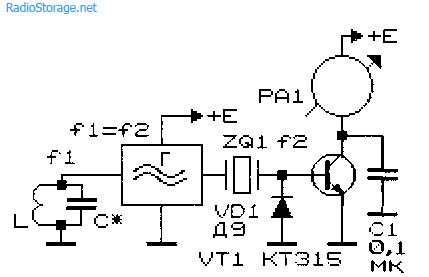
Rice. 9. Schematic diagram of a metal indicator.
It is made on diode VD1, transistor VT1, capacitor C1 and milliammeter (microammeter) PA1. A quartz resonator is connected between the output of the generator and the input of the high-frequency millivoltmeter. If the generation frequency f1 and the frequency of the quartz resonator f2 coincide, the needle of the device will be at zero. As soon as the generation frequency changes as a result of introducing a metal object into the field of the search coil, the needle of the device will deviate.
The operating frequencies of such metal detectors are usually in the range of 0.1...2 MHz. To initially set the generation frequency of this and other devices of similar purpose, a variable capacitor or a tuning capacitor connected in parallel with the search coil is used.
Typical metal detector with two generators
In Fig. Figure 10 shows a typical diagram of the most common metal detector. Its operating principle is based on the frequency beats of the reference and search oscillators.

Rice. 10. Diagram of a metal detector with two generators.

Rice. 11. Schematic diagram of the generator block for a metal detector.
A similar node, common to both generators, is shown in Fig. 11. The generator is made according to the well-known “three-point capacitive” circuit. In Fig. Figure 10 shows a complete diagram of the device. The design shown in Fig. 1 is used as search coil L1. 2 and 3.
The initial frequencies of the generators must be the same. The output signals from the generators through capacitors C2, SZ (Fig. 10) are fed to a mixer that selects the difference frequency. The selected audio signal is fed through the amplifier stage on transistor VT1 to the telephone capsule BF1.
Metal detector based on the principle of generation frequency interruption
The metal detector can also operate on the principle of disrupting the generation frequency. The diagram of such a device is shown in Fig. 12. If certain conditions are met (the frequency of the quartz resonator is equal to the resonant frequency of the oscillatory LC circuit with the search coil), the current in the emitter circuit of transistor VT1 is minimal.
If the resonant frequency of the LC circuit changes noticeably, the generation will fail, and the readings of the device will increase significantly. It is recommended to connect a capacitor with a capacity of 1 ... 100 nF in parallel to the measuring device.

Rice. 12. Circuit diagram of a metal detector that works on the principle of disrupting the generation frequency.
Metal detectors for searching for small objects
Metal detectors, designed to search for small metal objects in everyday life, can be assembled according to those shown in Fig. 13 - 15 schemes.
Such metal detectors also operate on the principle of generation failure: the generator, which includes a search coil, operates in a “critical” mode.
The operating mode of the generator is set by adjusted elements (potentiometers) so that the slightest change in its operating conditions, for example, a change in the inductance of the search coil, will lead to disruption of the oscillations. To indicate the presence/absence of generation, LED indicators of the level (presence) of alternating voltage are used.
Inductors L1 and L2 in the circuit in Fig. 13 contain, respectively, 50 and 80 turns of wire with a diameter of 0.7...0.75 mm. The coils are wound on a 600NN ferrite core with a diameter of 10 mm and a length of 100... 140 mm. The operating frequency of the generator is about 150 kHz.

Rice. 13. Circuit of a simple metal detector with three transistors.

Rice. 14. Scheme of a simple metal detector using four transistors with light indication.
Inductors L1 and L2 of another circuit (Fig. 14), made in accordance with the German patent (No. 2027408, 1974), have 120 and 45 turns, respectively, with a wire diameter of 0.3 mm [P 7/80-61 ]. A 400NN or 600NN ferrite core with a diameter of 8 mm and a length of 120 mm was used.
Household metal detector
A household metal detector (HIM) (Fig. 15), previously produced by the Radiopribor plant (Moscow), allows you to detect small metal objects at a distance of up to 45 mm. The winding data of its inductors are unknown, however, when repeating the circuit, you can rely on the data given for devices of similar purposes (Fig. 13 and 14).
Rice. 15. Scheme of a household metal detector.
Literature: Shustov M.A. Practical circuit design (Book 1), 2003
The purpose of a metal detector, or, as it is also called, a metal detector, is to search for metal products using electrical or magnetic properties that distinguish them from the environment. Simply put, using a metal detector you can find metal even in the ground. However, its capabilities are not limited to this environment, since it is also used in water. This device is used by security services, criminal service, military, geologists and workers of many other specialties. But detailed instructions for assembling a metal detector with your own hands can also be useful for using the device in the home.
Area of application of the device
For those who have lost a ring or keys and know their approximate location, a metal detector will be a real salvation. Making a homemade metal detector is not that difficult, especially if there is a diagram of a homemade metal detector and a detailed description of the assembly. Most often, the assembly is carried out by amateur radio mechanics, treasure hunters, local historians and military historical associations. The device makes it possible to find a coin in the top layer of soil or large metal parts at an impressive depth of up to 1.5 meters.
Homemade devices also have these properties, but with the help of an experienced radio mechanic you can assemble a more powerful device. Many people use a metal detector for commercial purposes: when various parts are found, they sell them for scrap metal, earning a certain amount. Finds can also be more important, for example, antiques or real treasures in the form of treasure chests.
Consists in the use of electromagnetic technology. The coil creates an electromagnetic field that interacts with conductive objects, resulting in an eddy current that distorts the coil signal. Even in the absence of current conductivity, an object may have its own magnetic field, which will also create interference, thereby indicating the location of the object.
After interference arrives, the electromagnetic pulse changes and goes directly to the control unit, which emits sound signals or displays data on the display indicating the finding. Devices are divided into many groups and have a huge number of names, and they are all classified according to many parameters.
Types of detectors
General characteristics of the devices:

Discrimination is a composite parameter, since there are most likely 1 or 2 signal outputs, and there are several definitions based on the property and location of the object. However, according to the reaction of the device, taking into account the approach to the object, signals stand out:
- Spatial - you can determine the location of the object in the search location and the depth of its location.
- Geometric - the ability to figuratively form the length and width of the find.
- Qualitative - the ability to speculate about the structure of the find.
Operating Parameters
All sensitivity parameters are related to the generator frequency. Therefore, initially metal detectors are classified depending on the operating frequency:

Method of searching for metal products
There are more than 10 search methods, however, methods with digitization of signals and processing through a computer belong to professional equipment. Do-it-yourself metal detector circuits most often are made taking into account the following search methods:
- Parametric.
- Transceiver.
- Accumulation phase.
- Beating.
Without take-up reel
 Parametric devices They have neither a pick-up coil nor a receiver. Detection occurs due to the influence of the object on the inductive coil of the generator. Depending on the quality factor of the coil, the frequency and amplitude of the oscillations will change, which can be recorded in different ways, for example:
- Frequency and amplitude are measured.
- The generator current is measured.
- PLL (Phase Locked Loop) loop voltage measurement.
In most cases, such devices are used as magnetic detectors. They have poor sensitivity, but are cheap and noise-resistant, and use requires a certain skill.
With built-in transmitter
Devices with receiver and transmitter are very effective, but have a complex circuit structure and require high-quality coils. Devices with one coil are called induction.
Clicking sounds after approaching an object
 In metal detectors with phase accumulation, they can be with one pulse-type coil or with two generators. In a device with one coil, as pulses pass, the phase shift increases and when a certain level is reached, the discriminator is triggered and a click-type signal is sent to the headphones. The closer the object, the more often the clicks are repeated.
Double coil metal detector In terms of circuit design, it is simpler than a pulsed one, but also weaker in sensitivity, penetration is also up to 2 times less.
Metal detectors on beat
The devices are assembled with 2 generators, a reference and a working one. The working generator is adjusted to a zero beat value and, depending on the sound tone, one can judge the location of the object, its size and properties.
DIY metal detector assembly
There is an opinion that branded metal detectors are superior to homemade devices in many respects . However, the facts say the opposite: If the device is assembled correctly, then the homemade product may turn out to be not only cheaper than the factory design, but also better. Many treasure hunters purchase the cheapest types of devices, and then they either assemble the metal detector themselves or buy a custom version.
A beginner or a person who is not well versed in electronics may find the special terminology, formulas and diagrams difficult. But with a detailed analysis of all the information, it becomes clear that with at least an average level of knowledge, you can figure out how to make a homemade metal detector.
Do-it-yourself printed circuit board manufacturing
For further placement of metal detector parts, a printed circuit board is needed. To do this, it is best to use the LUT method - laser-iron technology.
Manufacturing occurs in stages in the following sequence:

At the last stage, tinning of the paths is carried out. The LTI-120 solution is spread with a soldering iron.
Installation of radio components on the board
At this stage of metal detector assembly All elements are installed in the prepared board:

In this case, an old circuit is used, but you can find and solder a similar, modern version, since the K157UD2 amplifier is currently difficult to find.
Making a device coil
A homemade reel is wound on a rigid frame with a radius of 100 mm. Need to reel approximately 25 turns. This indicator is acceptable when using PEV wire with a diameter of about 0.5 mm, but other strong material can also be used.
To select the optimal number of turns, you can conduct an experiment by testing the device to catch a coin.
Frame and additional elements
A part from a portable receiver with an Ohm resistance can be used as a signal speaker. It is allowed to use Chinese analogues with the same resistance.
 For normal operation of the metal detector, need to adjust sensitivity. The threshold is determined when a uniform, but not very strong crackling is achieved. To do this, use two potentiometers with different powers. You will need one with a power of 10 kOhm, and the other with a power of 100 kOhm. To increase noise immunity, it is recommended to use a shielded cable to connect the coil to the circuit. The power source can be rechargeable batteries. The minimum voltage should be 12 V. To ensure stability of the electrical circuit, a voltage stabilizer type L7812 is installed at the output.
After making the structure and checking its functionality, you need to make the body of the portable device. Each amateur can create a frame at his own discretion from available items, but attention should be paid to the following recommendations:
- For convenience and better stability, the rod can be strengthened by purchasing several meters of PVC water pipe and several jumpers for connection. It is advisable to make a hand rest on the top part. The ideal option would be to make an armrest. In this case, it will be easier for the operator to use the metal detector.
- The board must be placed in a protected box appropriate to its size and secured to the case.
- The battery used for power supply is a screwdriver, which is lightweight and has sufficient capacity. Taking into account the parameters, some other option may be used.
- When creating the housing and the entire structure, it is necessary to take into account that the presence of foreign metal elements will greatly distort the signal of the magnetic field of the metal detector and its effectiveness will be impaired.
Device efficiency
 A device made according to this design, will not be effective when searching for small objects at great depths, but some Soviet coins can be found at a depth of about 30-40 cm, and the detector senses large metal parts at a distance of about 1 meter or more.
This homemade version of a metal detector is suitable for people who are learning the basics of detecting or who do not have the opportunity to use an expensive model. For specialists or experienced treasure hunters, the effectiveness of the device may not be enough.
In terms of its popularity, metal detecting is comparable to fishing or hunting, not inferior to them in excitement with a certain amount of commercialism. The increase in the technical culture of the population and the wide range of the market for electrical parts are contributing to the growth in the number of people who want to make their own metal detector with their own hands in order to try themselves as a treasure hunter. In Fig. Below is a metal detecting enthusiast using a homemade metal detector to detect metal items on the seashore.
The principle of operation of the metal detector
A metal detector (hereinafter referred to as MI), also called a metal detector, is an electronic device that generates a directed electromagnetic field (primary signal) and detects its changes when the field comes into contact with metal objects. During the propagation of electromagnetic waves in an inhomogeneous physical environment, they interact with metals, creating eddy currents on their surfaces that generate their own electromagnetic fields. The MI receiving equipment records these fields (secondary signal) and informs the searcher about the detected find by audio or visual means.
How does a metal detector work?
The technical implementation of the operating principle of the MI is based on the use of two basic functional elements of a modular type:
- search coils for generating a primary electromagnetic field of a directional nature and receiving re-reflected secondary radio signals;
- control units for processing information from search coils and providing the operator with the processing result.
Depending on the purpose of the MI, search coils operate in the following frequency ranges:
- low-frequency range within the range of 2.5-6.6 kHz - to detect gold, silver, copper and their alloys at a depth of up to 4 meters;
- in the mid-frequency range - for searching for metals of any type;
- in the high-frequency range - for searching aluminum, nickel and detecting small targets at shallow depths.
The parameters of the magnetic field induced on the surface of the metal target change as follows:
- the signal amplitude decreases with distance from the transmitter;
- the phase of the induced field is determined by the electrical conductivity of the metal.
Based on the difference in amplitude, the MI equipment calculates the distance to the target; based on the phase shift, the type of metal is determined.
In Fig. Below is a schematic diagram of the analysis of MI information.

Metal detector – detector or scanner
At their core, MIs are detector devices (from the Latin detector - detector), indicating changes in the parameters of the primary directional radio signal. The quality of metal detection directly depends on the level of complexity of the metal detector equipment that processes the secondary signal. At the initial stage of the emergence of MI, the operator was quite satisfied with the squeaking sound in the headphones that occurred when a metal target was detected. The development of the element base for microelectronics has significantly expanded the capabilities of manual metal detection. Professional hand-held metal detectors are capable of solving the following tasks:
- identification of the “find” by type of metal;
- determining the depth of its location;
- assessment of the size and configuration of the detected object.
Using the latest software developments, leading manufacturers have launched sales of MI with the ability to image a detected target. For example, the German company OKM has developed an in-depth 3D scanner (from the English scan - to examine) model EXP 6000, which displays the configuration of a metal object on the screen.
In Fig. Below is an EXP 6000 MI monitor with a target image displayed on the screen.

Types of MI by purpose
In accordance with their intended purpose, MI is divided into the following types:
- Soil models designed for underground surveys in the upper layers of soil. Devices in this category are the most common among metal detectors and treasure hunters who can assemble a metal detector with their own hands at home. The simplest homemade product has low accuracy and does not always distinguish between different types of metals. Professional instruments can detect small grains of gold, ignoring other metals.
- Depth models designed to detect targets at a depth of up to 6 meters. However, they can only “see” large objects with an area of over 400 square meters. see. Deep devices are in demand by engineering services as route finders, by geologists as specialized georadars for searching for native gold, etc.
- Underwater metal detecting devices operating underwater. They are subject to increased requirements for the tightness of the search system. The operating conditions of underwater MI in sea and fresh water differ significantly. Underwater detectors use only sound indication.
Note! Underwater MI can be used on the surface in the mode of a conventional ground metal detector. Searchers only need to adjust the length of the rod and the position of the stop to make it more convenient to use the device.
- Special metal detectors:
- security devices for detecting metal products in luggage, clothing or on a person’s body during inspection;
- industrial metal detectors as part of conveyor lines, signaling the presence of metals in products;
- military devices, collectively called mine detectors;
- detectors tuned exclusively to gold objects.
In Fig. Below is a hand-held security metal detector.

Motivation for choosing the design of a homemade metal detector
Long before assembling a metal detector at home, the craftsman needs to compare numerous factors that influence the operation of the detector and choose the optimal design option that fully meets his needs. When making a metal detector with your own hands, the following technical and operational indicators are taken into account:
- general parameters of the search device that determine its functionality;
- operating frequencies in the range of which it is intended to operate;
- a search method that determines the circuit design of the device, specifying a method for recording changes in the reaction of the MI when it approaches a metal object.
General parameters of MI
For homemade search equipment, the following parameters are distinguished:
- Penetrating ability, which characterizes the maximum depth of penetration of the electromagnetic field, deeper than which the device is no longer able to detect a metal object.
- Sensitivity, indicating the ability to detect small objects.
- Resolution, more often called MI discrimination, providing information about specific properties of an object. A metal detector requires full implementation of three components of discrimination:
- geometric – for judging the size and configuration of the found target;
- spatial – for information about the depth of the target and its location in the search area;
- by quality - for assumptions about the type of material of the object and its probable characteristics.
- The size of the search area within which metal can be detected.
- Selectivity - an increased reaction to finds of a given type (gold, non-ferrous metals, military artifacts, etc.).
- Noise immunity – lack of response to electromagnetic fields from extraneous sources.
- Energy consumption, which determines how long the device’s mobile power source will last for active operation.
In Fig. Below, in an ironic form, the process of metal detection (metal detecting) using a homemade MI is shown:
- pos. “A” – absence of metal targets;
- pos. “B” – metal objects of a certain value were discovered (for which the metal detecting was started).
The metal detector search area is highlighted in red.

Operating frequencies of homemade MI
The metal detector circuit and its assembly tie all the parameters of a homemade metal detector to the frequency range in which the operator expects to work. The practice of amateur metal detecting has shown the limited effectiveness of low-frequency (vlf) and high-frequency (hf) metal detectors, which require computer signal processing, consume a lot of energy and do not work well on mineralized wet soils. Most search engines interested in how to make a metal detector multifunctional in identifying and recognizing non-ferrous metals, ferrous metals, with minimal sensitivity to soil characteristics, focus on the low-frequency and mid-frequency ranges ranging from 30 kHz to 3 MHz. Operating in this frequency range allows the use of a simple metal detector to detect targets of any type of metal.
Search method
There are more than a dozen methods for finding metal objects using a directed electromagnetic field, including ultra-modern digital processing of the secondary signal on a computer when using MI professionally. When assembling homemade metal detectors for metal detecting at the amateur level, craftsmen focus on techniques that make it possible to simplify the circuit design of the detector as much as possible and reduce the cost of its configuration. The most popular methods for making homemade products are the following metal detection methods:
- parametric method, for the implementation of which a receiver is not needed;
- transceiver method - using a transmitter and receiver;
- method with phase accumulation - “until a click”;
- the beating method - “by squeaking”.
Parametric method
Parametric type metal detectors are equipped with only one coil, which is both transmitting and receiving. When a metal target is detected, the parameters of the generating coil change: inductance, frequency and amplitude of the generated oscillations, which is recorded by the MI equipment. The main problem when operating a detector without a receiver is the isolation of a relatively weak induced signal against the background of a powerful primary electromagnetic field.
Transceiver method
The design of models operating using the “receive-transmit” method has two coils:
- transmitting – for generating an electromagnetic field;
- receiving - for recording the signal re-emitted from a metal target.
Important! When assembling the transceiver MI, the coils must be positioned in such a way as to minimize the inductive coupling between them. If the axes of both coils are mutually perpendicular, the transmitter signal will not go directly to the receiving device and will not be listened to.
Metal detectors with phase accumulation (until a click)
The operation of phase-sensitive devices uses the process of delaying pulses during re-emission, which leads to an increase in the phase shift. When a specific value is reached, the discriminator is triggered and a click is heard in the headphones. As you approach a metal object, the clicks become more frequent, merging into a sound of a certain tonality. When the sound is adjusted appropriately, synchronization is disrupted directly above the object, and the sound disappears due to the transition of the click frequency to the ultrasonic range.
Metal detectors using beats (the “squeak” method)
If you make a metal detector using beats, then in your homemade design you need to use two electromagnetic field generators:
- a reference oscillator, the frequency of which is stabilized and is the reference frequency parameter;
- a working (search) generator, the frequency of which depends on the presence of metal in the search area.
Before the start of search work, the search generator is tuned to zero beats (frequency matching). When setting up, they achieve a low sound tone (squeak) so that it is convenient to search. By changing the tone, the properties of the detected object and its location are judged.
In Fig. Below is a homemade MI made from scrap materials.

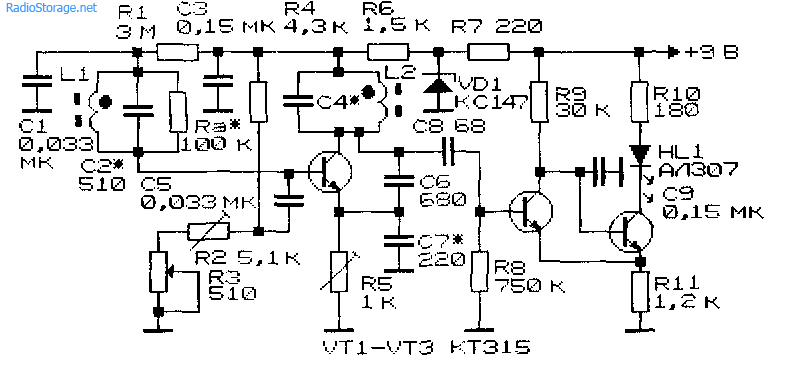
Schemes of homemade MI
Factory-made metal detecting equipment is presented on the market with quite expensive professional-level electronic systems, so enthusiasts constantly exchange information on how to make a homemade metal detector at home with minimal financial costs. Step-by-step instructions for assembling and debugging the device allow you to create a fully functional metal detector from available radio components. Metal detectors, including a do-it-yourself mine detector, the circuit of which is identical to those developed for standard MIs, are made using transistors and microcircuits. The kit for DIY circuits also includes:
- capacitors of various types: ceramic, film, electrolytic;
- resistors;
- resonators;
- controllers.
Additional Information. Quite often, circuits of amateur metal detecting equipment use the NE 555 microcircuit, which is a universal timer that generates single and repeating pulses with stable timing characteristics.
A worthy competitor to a metal detector on microcircuits is a metal detector on transistors, in which signals are generated using transistors KT-361 and KT-315 or similar radio components produced since Soviet times.
Do-it-yourself manufacturing of MI components
When designing a homemade metal detector, craftsmen focus on creating a small-sized, structurally balanced, relatively lightweight product. The mobile design and thoughtful ergonomics should minimize operator fatigue during hours of continuous search work, and high-quality assembly of the home-made structure will ensure good repeatability of results and high performance characteristics.
Homemade MI consists of the following components:
- control unit;
- frames with search coil;
- a holding rod on which the search coil and control unit are mounted.
Control block
To assemble the control unit, you need to select a box-type plastic case. The housing should compactly accommodate:
- printed circuit board with electronic filling, assembled in accordance with the circuit diagram;
- batteries;
- devices for sound and visual notification of a find.
The main element of the control unit is the printed circuit board.
Making your own MI printed circuit board
A printed circuit board is used for compact placement of radio components included in the MI circuit. Below is a generalized description of the stages of self-manufacturing a printed circuit board with a detailed description of the operations performed:
- The metal detector circuit is selected. In accordance with the diagram, a sketch of the board is drawn on paper by hand or printed on a printer.
- A piece of sheet PCB is cut to fit the dimensions of the board.
- Using any available method, the design is transferred to a textolite blank.
- The mounting locations for radio components are marked on the surface of the workpiece. Holes with a diameter of 1.0-1.5 mm are drilled.
- Using a permanent marker or a brush with varnish, traces are drawn in accordance with the paper template.
- The board is etched with ferric chloride or copper sulfate.
- After etching, the board is wiped and cleaned with sandpaper.
- Tinning operation is carried out.
In Fig. Below is a printed circuit board of the metal detector after tinning.

Frame with reel
The search frame of a metal detector is a flat, rigid body with a search coil mounted on it, designed to perform the following tasks:
- rigid fixation of the search coil relative to the holder rod;
- ensuring the constancy of the geometric dimensions of the emitting and receiving loops of the search coil;
- protecting coil wires from damage when the operator moves over rough terrain.
The body of the MI frame, round or rectangular in shape, is made of plastic tubes without the use of metal elements. PVC pipes with a nominal diameter of ½ inch (15 mm) are popular among craftsmen. Small frames are made non-separable in the form of a ring or square. When making a large rectangular body, it is appropriate to use fittings so as not to deform the tubes at bends. The size and shape of the housing must correspond to the size and configuration of the coil, taking into account the placement of the transmitting and receiving circuits in it.
The most important search element of the MI, which determines its operational characteristics, is the search coil.
MI coils
The functional properties of the MI are determined by the quality of manufacture of the search coil. The coil parameters and the general circuit of the metal detector need to be mutually adjusted until the optimal result is achieved. The performance of the coil is influenced by various factors, of which the following are decisive:
- coil dimensions;
- design of the coil ring;
- coil inductance value;
- degree of noise immunity;
- method of winding the wire of a basket coil;
- way to secure the coil.
Coil dimensions
Practice has shown that the efficiency of a coil directly depends on its size. Larger coils are able to penetrate deeper into the ground and cover a wider search area than their smaller diameter counterparts. The following gradation of search coil sizes is accepted:
- a diameter of 20-90 mm is optimal for searching for ferrous metal (fittings, profiles);
- diameter 130-150 mm is convenient for searching for so-called “beach gold”;
- diameter 200-600 mm is aimed at large metal objects.
Coil design
The classic design of a search coil is a monoloop (single loop), made in the form of a single flat ring of turns of copper wire. The width and thickness of the ring are selected 15-20 times less than the average diameter of the ring. Monoboop MIs are recommended for beginners to gain initial searching experience.
A more “advanced” design, compared to a monoloop, is the DD coil, which is a double detector (hence the name - from the English Double Detector). Structurally, the DD coil is made of two semicircles folded with an intersection. DD coils are highly sensitive, but on heterogeneous soils they can give a false signal.
Coil inductance
When assembling a MI at home, it is very important to ensure that the parameters of a self-made search coil match the parameters that are included in the selected detector circuit. The inductance value is influenced by the geometric dimensions of the coil, wire cross-section, number of turns, packing density and other factors. In networks you can find various methods for calculating inductance, simple formulas and nomograms with explanations of how to use them. Failure to follow these recommendations may result in the assembled circuit not working.
Coil noise immunity
Since the monoloop is designed similarly to a loop antenna, it is susceptible to a lot of interference. To expand the noise immunity capabilities of the device, simple devices such as:
- Faraday shield, which is a steel tube with braiding or foil winding;
- symmetrical windings of bifilar or cross type.
Basket reels
In Fig. Below is one of the modifications of the MI basket coil.

For all its advantages, the basket reel is endowed with two significant disadvantages:
- complexity and labor intensity of performing high-quality reliable winding;
- Calculation methods for flat and volumetric baskets differ significantly and require the use of appropriate computer programs.
Important! When making handicraft winding of a basket coil, the mandrel must be rigid and strong, since the total tension force of all the turns is large enough to deform or break the mandrel.
To prevent the wires stretched during winding from cutting through the coil frame, it is recommended to first glue pieces of durable plastic into the slots of the frame and only then begin winding.
Reel mount
Fastening the coil wire is quite often done on homemade frames made of plywood, plastic and other improvised materials, even on computer disks. Plywood has many disadvantages, including:
Polycarbonate-based plastics do not have these disadvantages. Moreover, two glued polymer disks form a sealed housing, expanding the possibilities of using the MI.
Homemade rod holder
The holder rod is the supporting element of the metal detector - the search coil and control unit are attached to it. The main requirement for the rod is the strength of the manufacturing material, since the holder is subject to constant weight load from the operator during search operations. Damage to the supporting structure can occur in rough terrain, forest plantations, and mountainous areas. Breakage of the rod may lead to forced cessation of search operations.
Note! There are no specific requirements for the metal detector rod; each MI user has the right to adjust the size and shape of the holder to his height and weight.
When independently manufacturing a metal detector for the housing of a rod-holder, elbow crutches (canadians) are often used as an initial semi-finished product, the design of which already provides for height adjustment of the stand and an armrest support. Also popular among craftsmen are telescopic fishing rods and ordinary metal-plastic water pipes, which are used to make full-fledged MI holders.
Homemade underwater metal detector
The process of manufacturing, assembling and setting up a metal detector designed for underwater metal detection is identical to the work on creating a conventional MI. However, it is necessary to point out two significant differences that accompany the manufacture of underwater MI:
- all equipment must be placed in a sealed housing that does not allow parts to come into contact with moisture;
- To report a discovery from under the water, it is advisable to use special light indicators.
Stages of making an underwater MI with your own hands:
- Selecting a circuit for working in river and sea water.
- Manufacturing of printed circuit board.
- Connecting the power supply.
- Placing the finished board with a power supply in a sealed container. Craftsmen recommend using a sealant tube as a housing. LED indicator lights are displayed on the outer surface of the tube. Each joint is additionally sealed with silicone sealant.
- Making a rod from a thin-walled stainless pipe or an ordinary plastic water pipe. The body of a fishing rod is used quite often.
Important! The bar should not be too light so as not to float, but also very heavy so as not to sink to the bottom.
- Fastening the assembled block with the printed circuit board to the rod.
- Winding the search coil. The reel body is a standard polypropylene pipe. The wound wire is filled with sealant.
- Soldering the coil leads to a stranded wire.
- Visual assessment of product tightness. Any cracks and joints that “do not inspire confidence” in terms of tightness are filled/covered with sealant.
- Checking for leaks in water.
Features of deep MI
Deep MI uses RF technology, which is effective in the high-frequency range. The transmitting and receiving coils are mutually perpendicular and can operate at several frequencies simultaneously. Deep devices are insensitive to small targets; their objects are large objects located in areas with differences in ground levels.
If you turn to the numerous forums of metal detecting enthusiasts that fill the Internet, you will notice the high level of manufacturing and adjustment of home-made structures that are described there. Self-made metal detectors are not inferior to factory-made search equipment, although they are many times cheaper. In Fig. Below is a homemade “deep sink”, the frame of which is made of durable polymer tubes.

Video