

Introduction and general principle of work by Kacher Brovin
Brovin's kacher is a type of blocking generator of electrical impulses with a relatively high frequency. The device can be assembled using various active elements, but most often bipolar or field-effect transistors are used during assembly. This device was invented by engineer Vladimir Ilyich Brovin in 1987. Moreover, it was invented rather by accident - Brovin was developing an electromagnetic compass that would allow one to determine the cardinal directions using sound. And as a sound generator, the engineer used a blocking generator he designed with a feedback circuit. The compass is working. But in the operation of the blocking generator, certain discrepancies with some laws of physics were noticed (for example, with the laws of Ampere and Biot-Savart, as well as with Kirchhoff’s law). That's how the kacher appeared.
Brovin came up with the name for his invention in 1996 based on the words “reactivity pump.” The author of the invention explains the operating principle of this or simply Brovin's kacher as follows:
In a conventional blocking oscillator, the transistor is turned on by the flow of current from a feedback coil in the base circuit of the transistor. In the case, in a non-obvious way (since in theory, the appearance of an electromotive force in the feedback coil can still open the transistor) will be closed all the time, and the current is generated due to the accumulation of electrical charges in the base of the transistor for further discharge when a certain threshold voltage is exceeded (so-called “avalanche breakdown”).
There are a great many opinions and reviews about this invention: from enthusiastic to skeptical. Here is the opinion of the inventor himself, taken from the forum http://club.1-info.ru (the author's spelling and punctuation have not been preserved):
Kacher is a transistor (radio tube) device with phenomenal qualities. Cheap (device costs less than $1) and does not require special technologies. Knowledge about the properties of casters is sufficient for widespread use in almost any industry, including ballet.
Since 2005, the topic of kacers has been discussed on many forums (type “Brovin Vladimir Ilyich” in a search engine). The opposition is completely suppressed, pay attention to the dates - the spitting continues until 2006.
Recognition of the existence of a new method of controlling a transistor is obvious.
There is no practical application (there is, but very little). Isn't it time, gentlemen, entrepreneurs, to start making money from this, and for you, government officials, to collect taxes?
Anticipating the question “Why not yourself”? I answer: “Because the 68th went. It's too late, doctor." "What to do?". Choose a topic - for example, “autoelectronics” - create a laboratory and start converting everything that is electrical in a car, as well as its production technology, into quality ones.
Perhaps someday this will be the case, but for now Brovin’s invention is just a fun toy for enthusiasts that has not found mass application in electronics or industry. Now let's move from theory to practice - let's make a Brovin kacher with our own hands.
Below is one of the diagrams of this quality device:

To make a Brovin kacher we will need the following parts:
- — 1 ferrite ring (height 0.7-0.8 cm, outer diameter 1.5-2 cm, inner diameter 0.5-0.7 cm);
- — 1 trimming resistor at 220 Ohm 0.25 W (R1);
- — 1 resistor at 1 kOhm 0.5 W (R2);
- — 2 transistors KT805 (with radiators) (VT1, VT2);
- — 1 rectifier diode 1A;
- — 1 capacitor 10000 uF 50V;
- — winding wire, 0.25 mm thick;
- - square copper wire, 1.5 square meters thick. mm (for primary coil);
- - square wire, 0.5 square meters thick. mm;
- - a small piece of plastic (can be cardboard, but not metal or metal-plastic!) tube, an ordinary plumbing pipe 1-1.5 cm thick and 20-30 cm long is quite suitable;
- - a tube, 4-7 centimeters thick (for the primary winding, you can take a half-liter plastic bottle);
- - planks for making a stand.
Stages of assembling the Brovin kacher
- 1. For the primary coil, take a square copper wire and wind it on any tube with a diameter of 4-7 centimeters - make 4 turns. We take out the tube, stretch the wire in length so that the height of the winding is 10-15 centimeters (about a third of the height of the secondary coil). Ready.
- 2. For the secondary coil, we wind a thin winding wire around a plastic pipe, making 800-1000 turns. Every few centimeters it is recommended to apply glue to the fresh turns, otherwise the winding may get confused and tangled. We install the primary winding around the bottom of the secondary coil (see photo below).
- 3. We assemble the remaining elements according to the diagram. The pipe must be secured in a vertical position; to do this, its end can be glued to the base (a board or even an unnecessary DVD). If the circuit does not work, try swapping the leads of the primary coil. It should help.
- 4. Adjustment of the assembled quality is carried out by adjusting the trimming resistor R1. Also, do not forget to install radiators on the transistors - they get quite hot.
Have you collected it? With bated breath, we bring an energy-saving lamp to the coil.

But this option is not the only possible one. Enthusiasts and Brovin himself developed many circuits, with various transistors, two or three coils, etc.
Attention! The site administration is not responsible for the content of methodological developments, as well as for the compliance of the development with the Federal State Educational Standard.
- Participant: Pishchulin Andrey Alexandrovich
- Head: Truntaeva Svetlana Yurievna
Introduction
At least once in our lives, we hear on TV or on the Internet about the great genius Nikola Tesla and his coil, which can transmit electricity through the air. But no one thought that at home you could assemble a similar device called the Brovin Kacher. In my work I want to show how you can use electrical appliances that are not connected to the network, and I will prove that this can be done at home without much expense.
Relevance The topic is due to the fact that the problem of finding clean energy in the 21st century is acute. In the modern world, humanity needs electricity every day. It is needed both by large enterprises and in everyday life. A lot of money is spent on its production. And that's why electricity bills are rising every year.
Object of study: physical phenomenon of contactless energy transfer.
Subject of study: a device that can transmit electricity wirelessly.
Hypothesis: Kacher Brovina can be assembled at home with minimal cost.
Target: make a working model of the Brovin Kacher and consider the possibilities of its practical application.
Tasks:
- study reference and scientific literature on this topic;
- consider the device, principle of operation and application of the Brovin kacher;
- create a working model of the Brovin quality player;
- analyze the knowledge gained on this topic.
Research methods:
- working with methodological literature
- comparative analysis
- observation
- experiment
Chapter I. Theoretical part
1.1. The device and principle of operation of the Brovin Kacher
The Brovin Kacher was invented in 1987 by Soviet radio engineer Vladimir Ilyich Brovin as an element of an electromagnetic compass. Engineer Brovin V.I. Higher education – graduated from the Moscow Institute of Electronic Technology in 1972. In 1987, he discovered inconsistencies with generally accepted knowledge in the operation of the electronic circuit of the compass he created and began to study them. He made many inventions at home. One of them is Kacher Brovina.
Let's take a closer look at what kind of device this is. Brovin's kacher is a type of generator assembled on a single transistor and operating, according to the inventor, in abnormal mode. The device exhibits mysterious properties that date back to the research of Nikola Tesla. They do not fit into any of the modern theories of electromagnetism. Apparently, Brovin's kacher is a kind of semiconductor spark gap in which the discharge of electric current passes through the crystalline base of the transistor, bypassing the stage of formation of an electric arc (plasma). The most interesting thing about the operation of the device is that after a breakdown, the transistor crystal is completely restored. This is explained by the fact that the operation of the device is based on reversible avalanche breakdown, in contrast to thermal breakdown, which is irreversible for a semiconductor. However, only indirect statements are given as evidence of this mode of operation of the transistor. No one, except the inventor himself, has studied the operation of the transistor in the described device in detail. So these are just assumptions by Brovin himself. So, for example, to confirm the “black” mode of operation of the device, the inventor cites the following fact: they say, no matter what polarity the oscilloscope is connected to the device, the polarity of the pulses shown by it will always be positive.
Maybe kacher is a type of blocking generator? There is also such a version. After all, the electrical circuit of the device strongly resembles an electrical pulse generator. Nevertheless, the author of the invention emphasizes that his device has a non-obvious difference from the proposed circuits. It provides an alternative explanation for the occurrence of physical processes inside the transistor. In a blocking oscillator, the semiconductor periodically opens as a result of the flow of electric current through the feedback coil of the base circuit. In quality, the transistor must be permanently closed in a so-called non-obvious way (since the creation of an electromotive force in the feedback coil connected to the base circuit of the semiconductor can still open it). In this case, the current generated by the accumulation of electrical charges in the base zone for further discharge, at the moment the threshold voltage value is exceeded, creates an avalanche breakdown. However, the transistors used by Brovin are not designed to operate in avalanche mode. A special series of semiconductors has been designed for this purpose. According to the inventor, it is possible to use not only bipolar transistors, but also field-effect and radio tubes, despite the fact that they have fundamentally different physics of operation. This forces us to focus not on research on the transistor itself in the quality, but on the specific pulse mode of operation of the entire circuit. In fact, Nikola Tesla was engaged in these studies.
Kacher Brovina is an original version of an electromagnetic oscillation generator. It can be assembled using various active radioelements. Currently, when assembling it, field-effect or bipolar transistors are used, less often radio tubes (triodes and pentodes). Kacher is a reactivity pump, as the author of the invention, Vladimir Ilyich Brovin, himself deciphered this abbreviation. The Brovin Kacher is powered by a modified 12 V, 2 A network adapter and consumes 20 W. It converts an electrical signal into a 1 MHz field with an efficiency of 90%. One of the parts of this device is a plastic pipe 80x200 mm. The primary and secondary windings of the resonator are wound on it. The entire electronic part of the device is located in the middle of this pipe. This circuit is completely stable, it can work for hundreds of hours without interruption. The Brovin Kacher with self-powering is interesting in that it is capable of lighting unconnected neon lamps at a distance of up to 70 cm.
1.2. Areas of use
The widespread practical application of new devices and products operating on the basis of this new physical phenomenon will make it possible to obtain a very significant economic, scientific and technical effect in various spheres and areas of human activity.
Let's consider the areas of application of this device:
1. New relays and magnetic starters based on the widespread use of kacher technology:
- can lead to a reduction in energy costs and an increase in production efficiency in general, which together will provide a very significant economic effect in the country’s economy;
2. Devices that illuminate fluorescent lamps (fluorescent lamps) not from 220 V, as now, but using KACHER technology products, from a supply voltage of 5 to 10 V:
- this will significantly reduce the level of fire and explosion hazards
3. Devices that provide the possibility of not serial (currently used), but parallel connection of individual solar battery elements:
- will significantly increase the reliability, durability and efficiency of their operation, as well as obtain a significant economic effect from their use;
4. Devices for inductive transmission of control information and energy between different traffic lights located on different sides of the intersection and included in one traffic light object (without the use of electrical wires currently used for this, with large labor costs for their installation):
- will save energy and costs.
1.3. Negative impact
Despite the positive aspects of using this device, one cannot fail to note its negative impact. While performing this practical work, I noticed that due to the strong electromagnetic field created near the camera, cell phones, cameras, and tablets fail. And here I thought that in addition to the positive aspects, this device has a negative effect, including on the human body. After reading the literature on this issue, I found out that a strong electromagnetic field has a negative effect on the human nervous system. Staying near a working device for a long time causes a headache, and upon close contact, a slight aching pain in the muscles of the arms. In addition, as it turned out, the kacher can emit ozone, which we can feel by the corresponding smell.
Also, do not touch the discharges with your hands; due to the high frequency, a small burn may remain on the skin. Thus, we can conclude that when working with this device it is necessary to follow the safety rules:
- Do not try to touch the discharges with your hands. The pain, if there is any, will not be severe, but you are guaranteed a burn.
- Keep pets away from the device.
- Keep mobile phones and other electronics away from the device.
- You should not stay near the switched on device for a long time.
Chapter II. Practical part
2.1. Assembling the Brovin quality camera installation
Let's consider the stages of assembling this device at home.
Basic elements of Kacher:
- inductor (secondary winding);
- inductor (primary winding);
- pay.
- frame
The diagram that I followed during assembly is as follows:

Installation details:
- Polyvinyl chloride (PVC) pipe with a diameter of at least 25 mm and a length of 30 cm (the glow range of the light bulbs will depend on this). I used a pipe with a diameter of about 55 mm.
- To make the secondary winding of the kacher, I used copper wire coated with a double layer of varnish and 0.20 mm in diameter. It should be wound on the pipe, at least 1500 turns. (My copy of the kacher has about 2000 turns wound on it.) Every few centimeters I applied glue to fresh turns, otherwise the winding might get lost and tangled.
- To make the primary winding, I needed a copper wire with a diameter of 0.5 cm, which must be wound around the secondary coil. It is necessary to make about 4 turns. We wind all the windings in one direction! We install and secure the pipe with the winding on plywood or a board, stretch the primary winding by 1/3 of the secondary. The windings must not touch! Then we fuse a metal wire the size of a sewing needle into the pipe from above and solder the end of the winding to it. Next, we screw the radiator for the transistor to the platform next to the coils, coat the base with heat-conducting paste and screw the transistor to the radiator with a metal socket.
To make the board I needed the following radio components:
- throttle,
- non-polar capacitor (1000 v 3000 μ F),
- 2 resistors (2.2 kOhm and 150 Ohm),
- NPN transistor, the more powerful the better (they can be found in a regular PC power supply or on the board of old tube TVs).
Everything is mounted as shown in the diagram (Fig. 1). Solder the power wires.

This device must be connected to a power supply with a voltage from 12 to 38 v, which I also designed myself (Fig. 3)

Checking the quality is carried out by placing a fluorescent light bulb on the secondary winding; if the connection is correct, it will light up. When the secondary winding is touched by a metal object, there will be a discharge between them. If the kacher does not work, then you need to check whether the circuit is assembled correctly or try changing the ends of the primary winding.
2.2. Effects observed during the operation of the Brovin quality camera
Let's consider the effects observed during the work of Kacher Brovin, which I constructed at home.
- We bring a fluorescent lamp to the secondary winding, we see that it lights up. (Fig. 4) If you bring a gas-discharge lamp to the kacher, it also begins to glow. (Fig. 5) The same effect is observed with other similar lamps. Also in a regular incandescent lamp you can see the so-called glow discharge. (Fig. 6)


- During operation, the kacher creates beautiful effects associated with the formation of various types of gas discharges - a set of processes that occur when an electric current flows through a substance in a gaseous state. Brovin's quality ranks:
- Streamer (from English Streamer) - dimly glowing thin branched channels that contain ionized gas atoms and free electrons split off from them. Streamer - visible ionization of air (glow of ions) created by an explosive - Kacher field. (Fig. 7)

- Arc discharge occurs in many cases. For example, with sufficient transformer power, if a grounded object is brought close to its terminal, an arc may light up between it and the terminal. Sometimes you need to directly touch the terminal with an object and then stretch the arc, moving the object to a greater distance. (Fig. 8)

Conclusion
Kacher Brovina is an original version of an electromagnetic oscillation generator. In my work, I proved that it is possible to make a working model of a kacher at home, and also considered the possibilities of its practical application. I would like to note that my work in this direction is not finished. In the future, I want to make a Brovin kacher with audio modulation. To do this, you need to complicate the circuit a little by adding two resistors and a transistor. (Fig. 9) Thus, we will be able to play music through the power supply circuit of the camera. In practice it looks beautiful and interesting.

As a result of the research carried out in this work, we can conclude that the Brovin Kacher is a simple device to manufacture and configure. With which you can demonstrate many beautiful and spectacular experiments. During the operation of the coil, we observed two types of discharges.
Analyzing all of the above, we can say that Kacher Brovina can be successfully used in alternative energy, for example, in devices for generating free electricity using permanent magnets.
In conclusion, it is necessary to emphasize the following: the creation of new technologies based on the described physical phenomenon can give Russia very significant advantages over other countries. Since, having carried out in the near future all the necessary studies of this physical phenomenon and developed a wide range of new devices and products operating on its basis and intended for wide practical application in various fields and spheres of human activity, Russia can make a new qualitative leap in its further technological development . The introduction of Russian know-how will radically change the entire energy infrastructure and society as a whole - when a new method of generating energy is suddenly discovered and experimentally confirmed.
For a long time I wanted to assemble a small Tesla coil or a Brovin kacher in order to do various experiments. A simple kacher did not inspire me, because the arcs from it were scanty. The idea was born to replace the bipolar transistor with a field switch.
The current consumption of the structure is from 1 to 2-3 amperes depending on the supply voltage. The supply voltage is 100-250 volts; if you use an appropriate field-effect transistor, the voltage can be increased.
For beginners, I’ll immediately say that streamers can squeeze a maximum of 20 centimeters. (here in the article there are streamers of 12-17 centimeters).
The operating principle is based on the generation of high-frequency pulses by a field operator.
You can replace absolutely everything in the circuit, but this will affect the operation of the device.
The device does not need configuration if everything is assembled correctly, but if it doesn’t work, then we look for a jamb in the circuit. If it doesn’t work and everything is assembled correctly, then we swap the outputs of the secondary, it should help. In order to accelerate the circuit and make the streamers larger, we make an oscillatory circuit in the L2 coil circuit. If you pick up a capacitor, the arcs will be loud and long. We select bias resistors from 10-60 kilo-ohms, power does not matter. Coil L1 is a choke from the lds, it also needs to be selected, the primary from the transformer will also work.
The cost of the device was 560 rubles, if you buy absolutely all the parts.
And of course a photo.


List of radioelements
| Designation | Type | Denomination | Quantity | Note | Shop | My notepad |
|---|---|---|---|---|---|---|
| VT1 | MOSFET transistor | IRFP460 | 1 | To notepad | ||
| VD1 | Diode | KD202B | 1 | To notepad | ||
| VD2, VD3 | Zener diode | KS147A | 2 | To notepad | ||
| C1 | Electrolytic capacitor | 100uF 450V | 1 | To notepad | ||
| C2 | Capacitor | 1uF 400V | 1 | To notepad | ||
| R1 | Resistor | 40 kOhm | 1 | To notepad | ||
| R2 | Resistor | 1 kOhm | 1 |
Kacher differs from a blocking generator in the electron plasma formed in the p-n junction, due to which we obtain a fairly high output voltage without the use of a high-voltage transformer. You can verify this if you assemble the simple diagram below. The only transformer in it is two windings on ferrite rings of 20 and 5 turns. Despite its simplicity, with a 12V supply, the circuit produces about 1700 Volts of pulse voltage at output X1 (without load).
The circuit can operate in two modes: economical (switch SA1 is open) and normal (contact SA1 is closed). In economy mode, with 12V power supply, the device consumes a current of 200..300mA.
The most interesting part in the circuit is the ferrite transformer TV1. It swings on two ferrite rings with a diameter of 10 mm folded together.  The collector winding is 5 turns, and the base winding is 20, and if the first one winds clockwise, then the second one winds counterclockwise. It is advisable to use the wire in fluoroplastic insulation, with a diameter of 0.05-0.3 mm. It is better to wind the collector winding with a thicker wire.
Different transistors were tested for this circuit. The following pattern emerged: the higher the nominal maximum collector-emitter voltage, and the steeper the I-V characteristic of the transistor, the higher the voltage can be obtained at the output. The pulsed high-voltage MJE13005 was ideal. It will need to be installed on a small radiator.
Chokes L1 and L2 are standard, 100 μH. Select capacitors for a voltage not lower than 100V.
Settings
Here you will need an oscilloscope with a high-impedance output, the probe of which must be placed next to output X1. It's better not to connect directly, because... High voltage may damage the oscilloscope. Set R1 to the middle position, open switch SA1, and connect 12V power. If the oscilloscope does not show black pulses, then change the terminals of the base winding TV1.

If you don’t have an oscilloscope, you can configure the device using the Avramenko plug. It needs to be connected with one single input to the output of the camera.
When the camera is running, the HL1 LED will light up despite the fact that the second end of this simple device is not connected anywhere.
Depending on the tasks being solved, it may be necessary to connect the pitcher to different loads. The simplest thing is to power a fluorescent lamp rated for 220V through a diode (preferably SF56) and a smoothing capacitor. With SA1 closed and a supply voltage of 15V, you can light a 10-watt light bulb.
Some tasks require fast charging of the capacitor to high voltages. This can be done according to the previous scheme, but the capacitor must be non-electrolytic and designed for a voltage of 2000V. Also, in this case, instead of one you need to install 4 diodes connected in series.
The most interesting connection is a long line, usually a coaxial cable. Its braid is connected to the common wire of the circuit, and the central core is connected to output X1.
What will happen if in the quality control circuit, instead of one transistor, you put two and make them work alternately? Read about it.
Materials used
- Korotkov D.A. Development and research of generators of high-power nanosecond pulses based on drift diodes with sharp recovery and diodes with deep levels
- Pichugina M.T. Powerful pulsed energy
Gorchilin Vyacheslav, 2014
* Reprinting of the article is possible provided that a link to this site is installed and copyright is respected.
Preface
This spring, I was faced with the task of creating a set of generators to test the stability of equipment under conditions of strong electrical discharges. In addition to the transistor-based HF generators that are familiar to me, which provide good HF field strength nearby, I needed a small high-voltage source. This is where I remembered the quality device of the Soviet radio engineer Vladimir Ilyich Brovin - a simple device that allows me to get the high voltage I need.
I assembled my first kacher back in the early 2000s. It was a fairly powerful device almost one meter high, producing a dense beam of corona discharges. It was a dangerous thing... Hair began to move a couple of meters from it... But now I need a compact, small coil that is safe to use. After examining the materials and parts I had, I got to work.
Device diagram
The quality circuit has reached our times practically unchanged and is a blocking oscillator on a single transistor. Currently, there are many variants of circuits for this device assembled using lamps, bipolar and field-effect transistors, but I settled on the simplest “classical” circuit.

“Classic” scheme of Brovin’s quality
Parts and materials
The device is based on two main elements - an inductively coupled coil and a transistor for generating oscillations. The transistor was chosen D1761(the first one that caught my eye and had the required parameters). As a coil frame, I used a piece of polypropylene plastic pipe with a diameter of 32 mm and a length of 140 mm. In addition, in the bins there was a coil with PEV-2 wire, 0.15 mm in diameter, which I used in the manufacture of the quality device.
Assembling the device
Stepping back 20 mm from the end of the tube, I wound 650 turns of wire (winding - turn to turn in one layer, without overlaps). In this case, the length of the coil winding L2 was 105 mm.
I soldered the mounting wires to the ends of the wire and secured them inside the tube to prevent damage to the winding. The entire winding was covered with two layers of acrylic varnish. I soldered a steel needle to the upper terminal of the coil and brought it out through a decorative plastic plug. I secured the coil body on the circuit board for easy setup and placement of the coil. L1.
![]()
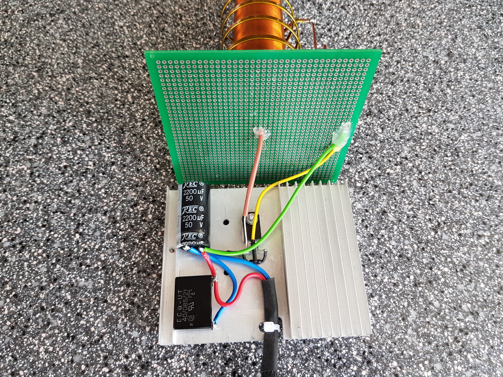
Brovin quality components![]()
![]()
Reel L1 I made it from a copper busbar, 3 mm wide. It is wound on a mandrel D 45 mm, only 5 turns with a small pitch. Here you need to remember that the direction of winding the turns is the same as that of coil L2. If the winding directions do not coincide, the generator will consume current, but there will be no high voltage at the output!
To connect the L1 coil to the circuit, I installed a screw connector. It turned out simple and convenient.
Since the pump circuit contains only 5 parts, I assembled it using a hinged installation, placing the parts on the radiator body.
Device setup
A correctly and carefully assembled generator from serviceable components almost always starts working. To obtain the maximum voltage, you can try to change the position and number of turns of the L1 coil, focusing on the size of the streamer and the current consumed. In my case, with a supply voltage of 24 volts, the coil consumes 0.85 A. For my task, this is optimal. In some cases, it may be necessary to select resistors in the base circuit.

Since my streamer is not very large, to visually indicate the operation of the coil and the presence of high voltage, I added a small neon light bulb to the body of the coil.

Conclusion
The Brovin Kacher is an easy-to-replicate and interesting device for studying high-voltage discharges in various environments. The very principle of its operation is interesting and mysterious... After all, the voltages generated by the high-voltage coil, and these are thousands and tens of thousands of volts, do not damage the transistor, although they are directly applied to the base of this semiconductor device.
In principle, there is a scientific explanation for this mystery (and more than one), but still, the very principle of operation of the device remains a subject of debate among scientists and experimenters, as well as enthusiasts engaged in the search for Free Energy and studying the legacy of Nikola Tesla. Perhaps you will be the one to solve this riddle...