

A selection of simple and interesting circuits for beginner radio amateurs. The main emphasis of the proposed designs is on simplicity and understanding of the operation of the basics of electronics. In addition, various methods for testing basic radio-electronic components such as diodes, transistors and optocouplers are considered, and the operation of the latter is also considered.
In this article, in a simple and convenient form, you will master the skills of using a multimeter. You will learn about ways to test the main radio components from which we will assemble our first electronic homemade products. You will learn how to test the assembled circuit with a multimeter and check the functionality of the diode, transistor and capacitor.
In this article, novice radio amateurs will be able to get acquainted with the conventional graphic designation of various types of radio components in circuit diagrams, accepted in world amateur radio practice.
Simple schemes for beginner Arduinists |
A series of articles and training diagrams with amateur radio experiments on the Arduino board for beginners. Arduino is an amateur radio construction toy, from which, without a soldering iron, etching of printed circuit boards, etc., any beginner in electronics can assemble a full-fledged working device, suitable for professional prototyping and for amateur experiments in the study of electronics. And besides, Arduino is a useful electronic gadget in a smart household.
How a semiconductor device called a transistor works and works, why it is so often found in radio equipment and why it is almost never possible to do without it.
Magnetization indicator- An ordinary school compass is sensitive to the magnetic field. It is enough, say, to pass the magnetized end of a screwdriver in front of its arrow and the arrow will deflect. But, unfortunately, after this the arrow will swing for some time due to inertia. Therefore, it is inconvenient to use such a simple device for determining the magnetization of objects. The need for such a measuring device often arises. An indicator assembled from several parts turns out to be completely non-inertial and relatively sensitive to, for example, determine the magnetization of a razor blade or a watch screwdriver. In addition, such a device will be useful in school when demonstrating the phenomenon of induction and self-induction
Alternating electromagnetic field indicator A magnetic field is formed around a conductor carrying current. If you turn on, say, a table lamp, then such a field will be around the wires supplying the mains voltage to the lamp. Moreover, the field will be variable, changing with a network frequency of 50 Hz. True, the field strength is low, and it can only be detected with a sensitive indicator
Hidden Wiring Finder. An alternating electromagnetic field can be detected using electronic devices; let's get acquainted with a more sensitive indicator that can detect the weak field of network wires through which alternating current flows. We will talk about finding hidden wiring in your apartment. This indicator will warn of damage to network wires when drilling holes in the wall
Power consumption indicator The “readings” of the previous indicators depend on the magnetic intensity. or an electric (as in the last indicator) field created by current flowing through the wires. The greater the current, the stronger the field. But current is nothing more than a characteristic of the power consumed by the load from the AC network. Therefore, it is not difficult to guess that an indicator, for example with an inductive sensor, can be used in circuits for monitoring and measuring power consumption. In addition, such an indicator circuit, installed near the front door, will signal before leaving the apartment that appliances have been left on. The best place to install the sensor is at the entrance of wires into the apartment, near the junction box. Therefore, the total current of all consumers connected to any socket in the apartment flows here. True, the alternating voltage at the terminals of the sensor coil will be small, and an amplifier will be needed
Telephone call indicator light If the TV is playing loudly in the room, the phone call may not be heard. This is where you need a light signaling device that will turn on the indicator circuit as soon as there is a phone call.
The basis of the automatic signaling device circuit is a sensor that responds to telephone calls, made on an inductance coil. It is located next to the telephone set, so its turns are in the magnetic field of the ringing bell electromagnet. The call signal induces an alternating emf in the sensor coil.
"Silent" sound scheme for beginners Sometimes you want to listen to the radio or watch TV without disturbing others? Of course, plug in headphones into the additional jacks, you say. That's right, but such a communication system is inconvenient - the connecting wire of the headphones does not allow you to move a significant distance, much less walk around the room. All this can be avoided if you use a “wireless” communication circuit consisting of a transmitter and receiver.
Electronic mine Using the principle of inductive coupling, you can assemble with your own hands an interesting circuit used in organizing competitions to search for “mines” - miniature transmitters hidden in the ground or indoors, operating at an audio frequency.
Each such “mine” is a multivibrator circuit operating at a frequency of approximately 1000 Hz. A power amplifier with an inductor as a load is included in the emitter circuit of the transistor of the multivibrator circuit. An electromagnetic field of sound frequency is formed around it
Intermittent siren Let's start with the simplest design, simulating the sound of a siren. There are single-tone sirens, which emit a sound of one tone, intermittent ones, when the sound smoothly increases and decreases, and then is interrupted or becomes single-tone, and two-tone ones, in which the tone of the sound periodically changes abruptly.
The intermittent electronic siren circuit is assembled using transistors VT 1 and VT 2 using an asymmetrical multivibrator circuit. The simplicity of the generator circuit is explained by the use of transistors of different structures, which made it possible to do without many of the parts necessary in the circuit for constructing a multivibrator using transistors of the same structure.
Two-tone siren. Looking at the circuit of this simulator, it is easy to notice an already familiar unit - a generator assembled on transistors VT 3 and VT 4. The previous simulator was assembled using this circuit. Only in this case the multivibrator does not operate in standby mode, but in normal mode. To do this, a bias voltage is applied to the base of the first transistor (VT 3) from the divider R 6 R 7. Note that transistors VT 3 and VT 4 have swapped places compared to the previous circuit due to a change in the polarity of the supply voltage.
Internal combustion engine. This is what you can say about the next simulator by listening to its sound. Indeed, the sounds produced by the dynamic head are reminiscent of the exhausts characteristic of the operation of a car, tractor or diesel locomotive engine.
To the sound of drops Drip... drip... drip... - sounds come from the street when it rains, in the spring drops of melting snow fall from the roof. These sounds have a calming effect on many people, and according to some, they even help them fall asleep. Well, maybe you need such a simulator. It will take only a dozen parts to build the circuit
Bouncing ball sound simulator Do you want to listen to a steel ball bouncing from a ball bearing on a steel and cast iron plate? Then assemble a simulator according to this scheme for beginner electronics engineers.
Sea surf... in the room By connecting a small set-top box to the amplifier of a radio, tape recorder or TV, you can get sounds reminiscent of the sound of the sea surf. The circuit of such a simulator consists of several nodes, but the main one is a noise generator
Bonfire... without flame Almost every pioneer camp has a pioneer bonfire. True, it is not always possible to collect enough wood so that the flame is high and the fire crackles loudly.
What if there is no firewood nearby? Or do you want to build an unforgettable pioneer bonfire at school? In this case, the proposed electronic simulator will help, creating the characteristic crackling sound of a burning fire. All that remains is to depict a “flame” from red scraps of fabric fluttering from a fan hidden on the floor.
How does a canary sing? This diagram for a beginner radio amateur is a relatively simple simulator of canary sounds. This is a multivibrator circuit already known to you, but an asymmetrical version of it (compare the capacitances of capacitors C1 and SZ of the frequency-setting circuits - 50 μF and 0.005 μF!). In addition, a communication chain consisting of capacitor C2 and resistor R3 is installed between the bases of the transistors. The elements of the multivibrator are selected so that it generates signals that, when received by the BF 1 headphone, are converted by it into sound vibrations similar to the trill of a canary
Nightingale trills in different voices Using part of the previous design, you can assemble a new simulator - the trill of a nightingale. It contains only one transistor, on which a blocking oscillator with two positive feedback circuits is made. One of them, consisting of a choke and a capacitor, determines the tonality of the sound, and the second, composed of resistors and a capacitor, determines the repetition period of the trills.
How does a cricket chirp? The cricket chirping simulator is an excellent circuit for a novice electronics engineer consisting of a multivibrator and an RC generator. The multivibrator circuit is assembled using transistors. Negative pulses of the multivibrator (when one of the transistors closes) flows through diode VD1 to capacitor C4, which is the “battery” of the bias voltage of the generator transistor.
Who said "meow"? This sound came from a small box, inside of which was an electronic simulator. Its circuit is a little reminiscent of the previous simulator, not counting the amplification part - an analog integrated circuit is used here.
Sound locator This simple toy is just a demonstration of the “work” of sound. It is named so because a real locator emits a signal, and then receives it already reflected from any obstacles. As soon as a certain distance remains to any obstacle, the received sound signal will increase to a level at which the automation will operate and turn off the electric motor.
Automatic "Hush" Noise interferes with any activity - this is clear to everyone. But sometimes we realize it too late, when in the classroom or other room where work is going on, the volume of our conversation or argument has long exceeded the permissible level. We should speak more quietly, but we get carried away and don’t notice that we are disturbing those around us.
If you install a machine in the room that monitors the sound volume, then when a certain, predetermined volume level is reached, the machine will work and light up the “Quiet” wall display or sound a beep.
"Trained Snake" An acoustic machine that responds to a sound signal can operate not only at a certain sound volume, but also at the corresponding frequency. The toy scheme proposed below has this selective property.
Single, 2, 3, and 4 channel acoustic switch Now let's talk about the circuits of automatic machines that can turn on and off the load using sound signals. Let's say, with one relatively loud signal (clapping your hands), the machine turns on the load to the network, and with another it turns it off. The breaks between claps can be as long as desired, and all this time the load will be either on or off. Such a machine is called an acoustic switch.
If the machine controls only one load, it can be considered single-channel, for example, a single-channel acoustic switch circuit
Diagram of a simple electric musical instrument. Any audio frequency generator produces electrical vibrations, which, when fed to an audio amplifier, are converted by its dynamic head into sound. The tonality of the latter depends on the oscillation frequency of the generator. When a set of resistors of different resistances is used in the generator circuit and they are included in the frequency-setting feedback circuit, you get a simple electric musical instrument on which you can play simple melodies.
Theremin diagram for beginners This is the first instrument that marked the beginning of a new direction in radio electronics - electronic music (electromusic for short). It was developed in 1921 by the young Petrograd physicist Lev Termen. An unusual electric musical instrument was named after the inventor. It is unusual in that it does not have a keyboard, strings or pipes with the help of which sounds of the desired tonality are obtained. Playing the theremin is reminiscent of the performance of a magician-illusionist - a wide variety of melodies sound from the dynamic head with barely noticeable manipulations with one or two hands near the metal rod-antenna sticking out on the body of the instrument.
Electronic drum diagram for a beginner electronic engineer The drum is one of the popular, but at the same time, bulky musical instruments. Reducing its dimensions and making it more convenient to transport is the desire of almost every ensemble. If you use the services of electronics and assemble an attachment to a powerful amplifier (and today it is an integral part of the ensemble’s equipment), you can get an imitation of the sound of a drum.
If you use a microphone, an amplifier and an oscilloscope to “view” the sound of a drum, you will be able to discover the following. The signal on the oscilloscope screen will flash in the form of a splash, reminiscent of a falling drop of water. True, it will fall from right to left. This means that the left side of the “drop” has a steep front, caused by hitting the drum, and then follows a damped decline - it is determined by the resonant properties of the drum. Inside, the “drop” is filled with almost sinusoidal vibrations with a frequency of 100...400 Hz - this depends on the size and design features of the instrument.
Electric guitar attachments The popularity of the electric guitar today is largely due to the ability to connect electronic attachments to it, allowing you to obtain a wide variety of sound effects. Among electric guitarists you can hear words unfamiliar to the uninitiated: “wah”, “booster”, “distortion”, “tremolo” and others. All these are the names of the effects obtained while playing melodies on an electric guitar.
The story will be about some consoles with a similar effect. All of them are designed to work both with industrial pickups installed on a regular guitar, and with homemade pickups made according to descriptions in popular amateur radio literature.
"Booster" attachment. If you hit one of the guitar strings with a pick and look at the shape of the electrical vibrations taken from the pickup terminals on an oscilloscope, it will resemble a filled pulse. The front of the “impulse” is steeper compared to the fall, and the “fill” is nothing more than almost sinusoidal oscillations modulated in amplitude. This means that when a string is struck, the volume of the sound increases faster than it decreases. Musicians call the rise time of sound an attack.
The dynamics of guitar performance will increase if you speed up the attack, i.e. increase the rate of rise of sound. The resulting sound effect is called “booster”. The attachment circuit for obtaining such an effect is discussed in this article. It is designed to work with bass guitar, which usually plays an important role in vocal and instrumental ensembles. Carrying out the rhythmic pattern of a musical composition, the bass guitar often becomes a solo instrument.
Color and music indicator If you integrate the circuit of such a set-top box into a radio receiver, then in time with the music the tuning scale will be illuminated with multi-colored lights or three color signals will flash on the front panel - the set-top box will become a color tuning indicator. As in the vast majority of color music consoles and installations, the proposed device uses frequency separation of audio frequency signals reproduced by a radio receiver into three channels.
Set-top box with small lamps The proposed set-top box circuit is a more serious design, capable of controlling multi-colored lighting on a small screen. The signal to the input of the set-top box still comes from the terminals of the dynamic head of the audio amplifier of the radio receiver or other radio device. Variable resistor R1 sets the overall brightness of the screen, especially along the high-frequency channel assembled on transistor VT1. The brightness of the lamps of other channels can be set with “your own” variable resistors - R2 and R3.
Attachment with car lamps Many of you, after making a simple color music console, will want to make a design that has greater brightness of the lamps, sufficient to illuminate a screen of impressive size. The task is feasible if you use car lamps with a power of 4...6 W. The circuit with car lamps works with such lamps
SCR-based set-top box An increase in the number of incandescent lamps requires the use of transistors in the output stages of the circuit, designed for a permissible power of several tens and even hundreds of watts. Such transistors are not widely sold, so SCRs come to the rescue. It is enough to use one thyristor in each channel - it will ensure the operation of an incandescent lamp (or lamps) with a power of hundreds to thousands of watts! Low-power loads are completely safe for the thyristor, and to control powerful loads it is mounted on a radiator, which allows excess heat to be removed from the thyristor body.
Four-channel color music set-top box This beginner's scheme can be considered more advanced (but also more complex) compared to the previous one. Because it contains not three, but four color channels and powerful illuminators are installed in each channel. In addition, instead of passive filters, active filters are used, which have greater selectivity and the ability to change the bandwidth (and this is necessary in the case of a clearer separation of signals by frequency).
A selection of simple circuits for young electronics engineers from the popular model designer magazine from old issues.
When studying electronics, the question arises of how to read electrical diagrams. The natural desire of a novice electronics engineer or radio amateur is to solder some interesting electronic device. However, at the initial stage, sufficient theoretical knowledge and practical skills are, as always, not enough. Therefore, the device is assembled blindly. And it often happens that a soldered device, on which a lot of time, effort and patience was spent, does not work, which only causes disappointment and discourages a novice radio amateur from getting involved in electronics, having never experienced all the delights of this science. Although, as it turns out, the scheme did not work due to a mere trivial mistake. It would take a more experienced radio amateur less than a minute to correct such an error.
This article provides useful recommendations that will help minimize the number of errors. They will help a novice radio amateur assemble various electronic devices that will work the first time.
Any radio-electronic equipment consists of individual radio components, soldered (connected) to each other in a certain way. All radio components, their connections and additional symbols are displayed on a special drawing. Such a drawing is called an electrical diagram. Each radio component has its own designation, which is correctly called conventional graphic designation, abbreviated as UGO. We will return to UGO later in this article.
 In principle, two stages can be distinguished in improving the reading of electrical circuits. The first stage is typical for installers of radio-electronic equipment. They simply assemble (solder) devices without delving into the purpose and operating principle of its main components. In fact, this is a boring job, although soldering is good, you still need to learn. Personally, I find it much more interesting to solder something that I fully understand how it works. There are many options for maneuvers. You understand which denomination, for example, is critical in this case, and which one can be neglected and replaced with another. Which transistor can be replaced with an analogue, and where should a transistor of the specified series be used only. Therefore, I personally prefer the second stage.
The second stage is inherent to developers of electronic equipment. This stage is the most interesting and creative, since one can improve endlessly in the development of electronic circuits.
Entire volumes of books have been written in this area, the most famous of which is “The Art of Circuit Design.” It is to this stage that we will strive to approach. However, this will require deep theoretical knowledge, but it’s all worth it.
Power supply designation
Any radio-electronic device is capable of performing its functions only in the presence of electricity. There are fundamentally two types of electricity sources: direct and alternating current. This article discusses sources exclusively. These include batteries or galvanic cells, rechargeable batteries, various types of power supplies, etc.
There are thousands of thousands of different batteries, galvanic cells, etc. in the world, which differ in both appearance and design. However, they are all united by a common functional purpose - to supply electronic equipment with direct current. Therefore, in the drawings of electrical circuits, sources are designated uniformly, but still with some minor differences.
It is customary to draw electrical circuits from left to right, that is, the same way as writing text. However, this rule is not always followed, especially by radio amateurs. But, nevertheless, this rule should be adopted and applied in the future.
 A galvanic cell or one battery, no matter “finger”, “pinky” or tablet type, is designated as follows: two parallel lines of different lengths. A longer dash indicates the positive pole – plus “+”, and a shorter one – minus “-”.
Also, for greater clarity, battery polarity signs may be indicated. The galvanic cell or battery has a standard letter designation G.
 However, radio amateurs do not always adhere to such encryption and often instead G write a letter E, which means that this galvanic cell is a source of electromotive force (EMF). The EMF value may also be indicated next to it, for example 1.5 V.
Sometimes, instead of a picture of the power supply, only its terminals are shown.
A group of voltaic cells that can be recharged repeatedly, battery. In the drawings of electrical circuits they are designated similarly. Only between the parallel lines is a dotted line and a letter designation is used G.B.. The second letter just means “battery”.
Designation of wires and their connections on diagrams
Electrical wires perform the function of combining all electronic elements into a single circuit. They act as a “pipeline” - they supply electronic components with electrons. Wires are characterized by many parameters: cross-section, material, insulation, etc. We will deal with installation flexible wires.
On printed circuit boards, conductive paths serve as wires. Regardless of the type of conductor (wire or track), in the drawings of electrical circuits they are designated in the same way - a straight line.
For example, in order to light an incandescent lamp, it is necessary to supply voltage from the battery using connecting wires to the light bulb. Then the circuit will be closed and a current will begin to flow in it, which will cause the filament of the incandescent lamp to heat up until it glows.

The conductor should be denoted by a straight line: horizontal or vertical. According to the standard, wires or live paths can be depicted at an angle of 90 or 135 degrees.
In branched circuits, conductors often intersect. If an electrical connection is not formed, then a dot is not placed at the intersection.

Common wire designation
In complex electrical circuits, in order to improve the readability of the diagram, the conductors connected to the negative terminal of the power source are often not shown. Instead, they use signs indicating the negative wire, which is also called generally th or weight or chassis or s earth.

Next to the grounding sign, especially in English-language circuits, the inscription GND is often written, abbreviated from GRAUND - Earth.

However, you should know that the common wire does not have to be negative; it can also be positive. It was especially often mistaken for the positive common wire in old Soviet circuits, which predominantly used transistors p— n— p structures.
Therefore, when they say that the potential at some point in the circuit is equal to some voltage, this means that the voltage between the indicated point and the “minus” of the power supply is equal to the corresponding value.
For example, if the voltage at point 1 is 8 V, and at point 2 it is 4 V, then you need to install the positive probe of the voltmeter at the corresponding point, and the negative probe to the common wire or negative terminal.

This approach is quite often used, since it is very convenient from a practical point of view, since it is enough to indicate only one point.
This is especially often used when setting up or adjusting radio-electronic equipment. Therefore, learning to read electrical circuits is much easier by using potentials at specific points.
Conventional graphic designation of radio components
The basis of any electronic device is radio components. These include LEDs, transistors, various microcircuits, etc. To learn how to read electrical circuits, you need to have a good knowledge of the conventional graphic symbols of all radio components.
For example, consider the following drawing. It consists of a battery of galvanic cells G.B.1 , resistor R1 and LED VD1 . The conventional graphic designation (UGO) of the resistor looks like a rectangle with two terminals. In the drawings it is indicated by the letter R, followed by its serial number, for example R1 , R2 , R5 etc.

Since an important parameter of a resistor, in addition to resistance, is , its value is also indicated in the designation.
The LED UGO has the shape of a triangle with a line at its apex; and two arrows, the tips of which are directed from the triangle. One terminal of the LED is called the anode, and the second is called the cathode.

An LED, like a “regular” diode, passes current in only one direction - from the anode to the cathode. This semiconductor device is designated VD, and its type is indicated in the specification or in the description of the circuit. The characteristics of a particular type of LED are given in reference books or “datasheets”.
How to read electrical diagrams for real
Let's return to the simplest circuit consisting of a battery of galvanic cells G.B.1 , resistor R1 and LED VD1 .
As we see, the circuit is closed. Therefore, electric current flows in it I, which has the same meaning since all elements are connected in series. Direction of electric current I from the positive terminal G.B.1 through a resistor R1 , Light-emitting diode VD1 to the negative terminal.
The purpose of all elements is quite clear. The ultimate goal is to light up the LED. However, so that it does not overheat and fail, the resistor limits the amount of current.
The voltage value, according to Kirchhoff’s second law, may differ on all elements and depends on the resistance of the resistor R1 and LED VD1 .
If you measure the voltage with a voltmeter R1 And VD1 , and then add the resulting values, then their sum will be equal to the voltage at G.B.1 : V1 = V2 + V3 .

Let's assemble a real device using this drawing.

Adding radio components
Consider the following circuit, consisting of four parallel branches. The first one is just a battery G.B.1, voltage 4.5 V. Normally closed contacts are connected in series in the second branch K1.1 electromagnetic relay K1 , resistor R1 and LED VD1 . Further along the drawing there is a button S.B.1 .

The third parallel branch consists of an electromagnetic relay K1 shunted in the opposite direction by a diode VD2 .
The fourth branch has normally open contacts K1.2 and boozer B.A.1 .
There are elements here that we have not previously considered in this article: S.B.1 – this is a button without fixing the position. While it is pressed, the contacts are closed. But as soon as we stop pressing and remove our finger from the button, the contacts open. Such buttons are also called tact buttons.

The next element is an electromagnetic relay K1 . Its operating principle is as follows. When voltage is applied to the coil, its open contacts close and its closed contacts open.

All contacts that correspond to the relay K1 , are designated K1.1 , K1.2 etc. The first digit indicates that they belong to the corresponding relay.
Boozer
WITH The next element, previously unknown to us, is the boozer. The buzzer can to some extent be compared to a small speaker. When an alternating voltage is applied to its terminals, a sound of the corresponding frequency is heard. However, in our circuit there is no alternating voltage. Therefore, we will use an active buzzer, which has a built-in alternating current generator.

Passive Boozer – for alternating current .
Active boozer – for direct current.
The active buzzer has a polarity, so you should adhere to it.
Now we can look at how to read an electrical diagram as a whole.
In the original state the contacts K1.1 are in a closed position. Therefore, current flows through the circuit from G.B.1 through K1.1 , R1 , VD1 and returns again to G.B.1 .
When the button is pressed S.B.1 its contacts close and a path is created for current to flow through the coil K1 . When the relay has received power its normally closed contacts K1.1 open, and normally closed contacts K1.2 are closed. As a result, the LED goes out VD1 and a buzzer sound is heard B.A.1 .
Now let's return to the parameters of the electromagnetic relay K1 . The specification or drawing must indicate the series of the relay used, for example H.L.S.‑4078‑ DC5 V. Such a relay is designed for a nominal operating voltage of 5 V. However, G.B.1 = 4.5 V, but the relay has a certain operating range, so it will work well at a voltage of 4.5 V.
To select a buzzer, it is often enough to know only its voltage, but sometimes you also need to know the current. You should also not forget about its type - passive or active.
Diode VD2 series 1 N4148 designed to protect elements that open the circuit from overvoltage. In this case, you can do without it, since the circuit is opened by a button S.B.1 . But if it is opened by a transistor or thyristor, then VD2 must be installed.
Learning to read circuits with transistors
In this drawing we see VT1 and engine M1 . To be specific, we will use a transistor of the type 2 N2222 who works in .

In order for the transistor to open, you need to apply a positive potential to its base relative to the emitter - for n— p— n type; For p— n— p type you need to apply a negative potential relative to the emitter.
Button S.A.1 with fixation, that is, it retains its position after pressing. Engine M1 direct current.
In the initial state, the circuit is open by contacts S.A.1 . When the button is pressed SA1 multiple paths for current flow are created. The first way is “+” G.B.1 - contacts S.A.1 – resistor R1 – transistor base-emitter junction VT1 – «-» G.B.1 . Under the influence of current flowing through the base-emitter junction, the transistor opens and a second current path is formed - “+” G.B.1 – S.A.1 – relay coil K1 – collector-emitter VT1 – «-» G.B.1 .
Having received power, the relay K1 closes its open contacts K1.1 in the engine circuit M1 . This creates a third path: "+" G.B.1 – S.A.1 – K1.1 – M1 – «-» G.B.1 .
Now let's summarize everything. In order to learn to read electrical circuits, at first it is enough just to clearly understand the laws of Kirchhoff, Ohm, electromagnetic induction; methods of connecting resistors, capacitors; You should also know the purpose of all elements. Also, at first, you should assemble those devices for which there are the most detailed descriptions of the purpose of individual components and assemblies.
My very useful course for beginners will help you understand the general approach to developing electronic devices from drawings, with many practical and visual examples. After completing this course, you will immediately feel that you have moved from a beginner to a new level.
Since you have decided to become a self-taught electrician, then probably after a short period of time you will want to make some useful electrical appliance for your home, car or cottage with your own hands. At the same time, homemade products can be useful not only in everyday life, but also made for sale, for example. In fact, the process of assembling simple devices at home is not difficult at all. You just need to be able to read diagrams and use the ham radio tool.
As for the first point, before you start making electronic homemade products with your own hands, you need to learn how to read electrical circuits. In this case, ours will be a good helper.
Among the tools for novice electricians, you will need a soldering iron, a set of screwdrivers, pliers and a multimeter. To assemble some popular electrical appliances, you may even need a welding machine, but this is a rare case. By the way, in this section of the site we even described the same welding machine.
Special attention should be paid to available materials, from which every novice electrician can make basic electronic homemade products with their own hands. Most often, old domestic parts are used in the manufacture of simple and useful electrical appliances: transformers, amplifiers, wires, etc. In most cases, novice radio amateurs and electricians just need to look for all the necessary tools in a garage or shed in the country.
When everything is ready - the tools have been collected, spare parts have been found and minimal knowledge has been obtained, you can proceed to assembling amateur electronic homemade products at home. This is where our small guide will help you. Each instruction provided includes not only a detailed description of each stage of creating electrical appliances, but is also accompanied by photo examples, diagrams, as well as video lessons that clearly show the entire manufacturing process. If you do not understand some point, you can clarify it under the entry in the comments. Our specialists will try to advise you in a timely manner!
Amateur radio technology. The book talks about the technology of amateur radio work. Recommendations are given for processing materials, winding coils and transformers, installing and soldering parts. The manufacture of homemade parts of structural elements, simple machines, fixtures and tools is described.

Digital electronics for beginners. The basics of digital electronics are presented in a simple and accessible way for beginners - by creating fun and educational devices using transistors and microcircuits on a breadboard, which immediately after assembly begin to work, without requiring soldering, adjustment or programming. The set of necessary parts is reduced to a minimum both in the number of items and in cost.
As the presentation progresses, questions are given for self-testing and consolidation of the material, as well as creative tasks for independent development of diagrams.

Oscilloscopes. Basic principles of measurements. Oscilloscopes are an essential tool for anyone who designs, manufactures, or repairs electronic equipment. In today's fast-paced world, professionals need the best equipment to quickly and accurately solve their critical measurement needs. As engineers' eyes into the world of electronics, oscilloscopes are key tools when studying the internal processes of electronic circuits.
![]()
Designing and building a Tesla coil is quite easy. This seems like a difficult task for a beginner (I found it difficult too), but you can get a working coil by following the instructions in this article and doing a little math. Of course, if you want a very powerful coil, there is no way other than studying the theory and doing a lot of calculations.

Homemade products of a young radio amateur. The book describes sound simulators, hidden electrical wiring finders, acoustic switches, automatic sound control models, electric musical instruments, attachments for electric guitars, color music attachments and other structures assembled from available parts.

School radio station ShK-2 - Alekseev S.M. The brochure describes two transmitters and two receivers operating on the 28 and 144 MHz bands, a modulator for anode-screen modulation, a power supply and simple antennas. It also talks about the organization of students' work at a collective radio station, the training of operators, the content of their work, and the research work of schoolchildren in the field of HF and VHF distribution.

Electronics For Dummies
Build your electronics workbench - and begin creating fun electronics projects right away
Packed with hundreds of colorful diagrams and photographs, this book provides step-by-step instructions for experiments that show you how electronic components work, advice on choosing and using essential tools, and exciting projects you can build in 30 minutes or less. You"ll get charged up as you transform theory into action in chapter after chapter!

The book consists of descriptions of simple designs containing electronic components and experiments with them. In addition to traditional designs, whose operating logic is determined by their circuitry, descriptions of products that are functionally implemented using programming have been added. The subject of the products is electronic toys and souvenirs.

How to master radio electronics from scratch. If you have a great desire to be friends with electronics, if you want to create your own homemade products, but don’t know where to start, use this tutorial. You will learn how to read circuit diagrams, work with a soldering iron, and create many interesting homemade products. You will learn how to use a measuring device, design and create printed circuit boards, learn the secrets of many professional radio amateurs. In general, you will gain enough knowledge to further master electronics on your own.

Soldering is easy - a step-by-step guide for beginners. The comic, despite its format and volume, explains in small details the basic principles of this process, which are not at all obvious to people who have never held a soldering iron in their hands (as practice shows, for many who have too). If you have long wanted to learn how to solder yourself, or are planning to teach it to your children, then this comic is for you.

Electronics for the curious. This book was written especially for you who are starting an exciting climb to the heights of electronics. A dialogue between the author of the book and a beginner helps to master the process. Measuring instruments, breadboards, books and PCs also help in mastering knowledge.

Encyclopedia of a young radio amateur. Here you will find many practical diagrams of both individual units and blocks, and entire devices. A special reference book will help resolve many issues. Using a convenient search system, you will find the desired section, and as visual examples there will be beautifully executed drawings.

The book was created specifically for beginning radio amateurs, or, as we also like to say, “dummies.” She talks about the basics of electronics and electrical engineering necessary for a radio amateur. Theoretical questions are presented in a very accessible form and to the extent necessary for practical work. The book teaches you how to solder correctly, take measurements, and analyze circuits. But rather, this is a book about entertaining electronics. After all, the basis of the book is amateur radio homemade products that are accessible to a beginning radio amateur and useful in everyday life.

This is the second book in a series of publications addressed to the beginning radio amateur as an educational and practical guide. In this book, on a more serious level, acquaintance with various circuits based on semiconductor and radio-vacuum, the fundamentals of sound engineering, electrical and radio measurements is continued. The presentation is accompanied by a large number of illustrations and practical diagrams.

ABC of a radio amateur. The main and only purpose of this book is to introduce children who do not have the slightest idea about it to amateur radio. The book is built on the principle “from the basics - through familiarity - to understanding” and can be recommended to middle and high school students as a guide to the beginnings of radio engineering.
For novice electronics engineers, it is important to understand how parts work, how they are drawn on a diagram, and how to understand an electrical circuit diagram. To do this, you first need to become familiar with the operating principle of the elements, and in this article I will tell you how to read electronic circuits using examples of popular devices for beginners.
Diagram of a table lamp and LED flashlight
A diagram is a drawing in which the details of the circuit are depicted using certain symbols, and their connections are depicted with lines. Moreover, if the lines intersect, then there is no contact between these conductors, and if there is a point at the intersection, this is a junction of several conductors.
In addition to icons and lines, the diagram shows letter designations. All designations are standardized, each country has its own standards, for example in Russia they adhere to the GOST 2.710-81 standard.

Let's start studying with the simplest thing - the diagram of a table lamp.
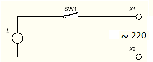
Schematics are not always read from left to right and top to bottom, it is better to go from the power source. What can we learn from the diagram, look at the right side of it. ~ means AC power.
Next to it is written “220” - a voltage of 220 V. X1 and X2 - are supposed to be connected to an outlet using a plug. SW1 - this is how a key, toggle switch or button is depicted in an open state. L - conventional image of an incandescent light bulb.
Brief conclusions:
The diagram shows a device that is connected to a 220 V AC network using a plug into a socket or other plug-in connections. It is possible to turn it off using a switch or button. Needed to power an incandescent lamp.
It seems obvious at first glance, but a specialist must be able to draw such conclusions by looking at the diagram without explanation; this skill will make it possible to diagnose a malfunction and eliminate it, or assemble devices from scratch.
Let's move on to the next diagram. This is a battery-powered flashlight with an emitter installed in it.

Take a look at the diagram, perhaps you will see new images for yourself. The power source is shown on the right, this is what a battery or accumulator looks like, the long terminal is plus another name - Cathode, the short one is minus or Anode. For an LED, a plus is connected to the anode (the triangular part of the designation), and a minus is connected to the cathode (looks like a strip on the UGO).
It is necessary to remember that for power sources and consumers the names of the electrodes are reversed. Two arrows emanating from the LED let you know that this device EMMITS light; if the arrows were pointing at it on the contrary, it would be a photodetector. Diodes have the letter designation VDx, where x is the serial number.
Important:
The parts in the diagrams are numbered in columns from top to bottom, from left to right.
If you add a stabilization unit built to the circuit, the voltage of the power supply will be stabilized. In this case, only from an increase in the supply voltage, with drawdowns lower than Ustabilization, the voltage will pulsate in time with the drawdowns. VD1 is a zener diode, they are switched on in reverse bias (cathode to a point with positive potential). They differ in the magnitude of the stabilization current (Istab) and stabilization voltage (Ustab).

Brief summary:
What can we understand from this diagram? What . It is connected by the primary side (input) to an alternating current network with a voltage of 220 Volts. At its output it has two detachable connections - “+” and “-” and a voltage of 12 V, unstabilized.

Let's move on to even more complex circuits and get acquainted with other elements of electrical circuits.