

In this article we will talk about color music. Probably every beginning radio amateur, and not only others, at one time or another had the desire to assemble color music. What this is, I think, is known to everyone - to put it simply, it is the creation of visual effects that change to the beat of the music.
That part of color music that emits light can be performed using powerful lamps, for example, in a concert setup; if color music is needed for home discos, it can be done using ordinary 220 volt incandescent lamps, and if color music is planned, for example, as computer modding, for everyday use, it can be done with LEDs.

Recently, with the advent of LED strips on sale, color and music consoles using such LED strips are increasingly used. In any case, to assemble Color Musical Installations (CMUs for short) a signal source is required, which can be a microphone with several amplifier stages assembled.

Also, the signal can be taken from the linear output of a device, a computer sound card, from the output of an mp3 player, etc., in this case an amplifier will also be required, for example, two stages on transistors; for this purpose I used KT3102 transistors. The preamplifier circuit is shown in the following figure:

The following is a diagram of a single-channel color music with a filter, working in conjunction with a preamplifier (above). In this circuit, the LED flashes along with the bass (low frequencies). To match the signal level, a variable resistor R6 is provided in the color music circuit.

There are also simpler color music circuits that any beginner can assemble, using 1 transistor, and also not requiring a preamplifier; one of these circuits is shown in the picture below:

Color music on a transistor
The pinout diagram for the Jack 3.5 plug is shown in the following figure:

If for some reason it is not possible to assemble a pre-amplifier using transistors, you can replace it with a transformer turned on as a step-up. Such a transformer must produce voltage on the windings of 220/5 Volts. The transformer winding with a smaller number of turns is connected to a sound source, for example, a radio tape recorder, parallel to the speaker, and the amplifier must produce a power of at least 3-5 watts. A winding with a large number of turns is connected to the color music input.
![]()
Of course, color music is not only single-channel, it can be 3, 5 or more multi-channel, when each LED or incandescent lamp blinks while reproducing the frequencies of its range. In this case, the frequency range is set by using filters. In the following circuit, a three-channel color music system (which I recently assembled myself), there are capacitors as filters:

If we wanted to use not individual LEDs in the last circuit, but an LED strip, then the current-limiting resistors R1, R2, R3 should be removed from the circuit. If the strip or LED is used RGB, it must be made with a common anode. If you plan to connect long LED strips, then to control the strip you should use powerful transistors installed on radiators.

Since LED strips are designed for 12 Volt power supply, we should accordingly raise the power supply in the circuit to 12 Volts, and the power supply should be stabilized.
Thyristors in color music
Until now, the article has only talked about color and music devices using LEDs. If there is a need to assemble a digital control unit using incandescent lamps, then thyristors will need to be used to control the brightness of the lamps. What is a thyristor anyway? This is a three-electrode semiconductor device, which accordingly has Anode, Cathode And Control electrode.

KU202 Thyristor
The figure above shows the Soviet thyristor KU202. Thyristors, if you plan to use them with a powerful load, also need to be mounted on a heat sink (radiator). As we see in the figure, the thyristor has a thread with a nut and is attached similarly to powerful diodes. Modern imported ones are simply equipped with a flange with a hole.

One of these thyristor circuits is shown above. This is a three-channel color music circuit with a step-up transformer at the input. In the case of selecting thyristor analogues, you should look at the maximum permissible voltage of the thyristors, in our case for the KU202N it is 400 volts.

The figure shows a similar color music diagram to the one shown above, the main difference in the lower diagram is that there is no diode bridge. Also, LED color music can be built into the system unit. I assembled such a three-channel color music with a preamplifier in a casing from a cider. In this case, the signal was taken from the computer’s sound card using a signal divider, the outputs of which connected active acoustics and color music. It is possible to adjust the signal level, both overall and separately by channel. The preamplifier and color music were powered from a 12 Volt Molex connector (yellow and black wires). The preamplifier and three-channel color music circuits for which they were assembled are shown above. There are other LED color music schemes, for example this one, also three-channel:

In this circuit, unlike the one I assembled, inductance is used in the mid-frequency channel. For those who want to first assemble something simpler, here is the following diagram for 2 channels:

If you collect color music using lamps, you will have to use light filters, which in turn can be either homemade or purchased. The figure below shows the filters that are commercially available:

Some fans of color and musical effects assemble devices based on microcontrollers. Below is a diagram of four-channel color music on the AVR tiny 15 MK:

The Tiny 15 microcontroller in this circuit can be replaced with tiny 13V, tiny 25V. And at the end of the review, I would like to say on my own that color music using lamps is inferior in terms of entertainment to color music using LEDs, since lamps are more inertial than LEDs. And for self-repetition, I can recommend this one:
Almost every novice radio amateur, and not only others, had a desire assemble a color music console or running fire to add variety to your music listening experience in the evening or on holidays. In this article we will talk about a simple color music console assembled on LEDs, which even a novice radio amateur can assemble.
1. The operating principle of color music consoles.
Operation of color music consoles ( CMP, CMU or SDU) is based on frequency division of the spectrum of an audio signal with its subsequent transmission through separate channels low, average And high frequencies, where each channel controls its own light source, the brightness of which is determined by the vibrations of the sound signal. The end result of the console's operation is to obtain a color scheme that matches the piece of music being played.
To obtain a full gamut of colors and the maximum number of color shades, color music consoles use at least three colors:

The frequency spectrum of the audio signal is divided using LC- And RC filters, where each filter is tuned to its own relatively narrow frequency band and passes through only vibrations of this part of the audio range:
1
. Low pass filter(low-pass filter) transmits vibrations with a frequency of up to 300 Hz and the color of its light source is chosen red;
2
. Mid Pass Filter(PSC) transmits 250 – 2500 Hz and the color of its light source is chosen green or yellow;
3
. High pass filter(HPF) transmits from 2500 Hz and above, and the color of its light source is chosen blue.

There are no fundamental rules for choosing the bandwidth or color of the lamps, so each radio amateur can use colors based on the characteristics of his perception of color, and also change the number of channels and frequency bandwidth at his own discretion.
2. Schematic diagram of a color music console.
The figure below shows a diagram of a simple four-channel color and music set-top box assembled using LEDs. The set-top box consists of an input signal amplifier, four channels and a power supply that supplies the set-top box with AC power.

The audio frequency signal is supplied to the contacts PC, OK And General connector X1, and through resistors R1 And R2 goes to the variable resistor R3, which is a regulator of the input signal level. From the middle terminal of the variable resistor R3 sound signal through a capacitor C1 and resistor R4 goes to the input of a pre-amplifier assembled on transistors VT1 And VT2. The use of an amplifier made it possible to use the set-top box with almost any audio source.
From the output of the amplifier, the audio signal is supplied to the upper terminals of trimming resistors R7,R10, R14, R18, which are the load of the amplifier and perform the function of adjusting (tuning) the input signal separately for each channel, and also set the desired brightness of the channel LEDs. From the middle terminals of the trimming resistors, the audio signal is supplied to the inputs of four channels, each of which operates in its own audio range. Schematically, all channels are designed identically and differ only in RC filters.
Per channel higher R7.
The channel bandpass filter is formed by a capacitor C2 and passes only the high-frequency spectrum of the audio signal. Low and medium frequencies do not pass through the filter, since the capacitor resistance for these frequencies is high.
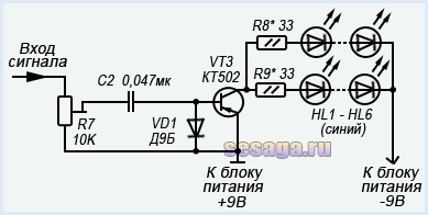
Passing the capacitor, the high-frequency signal is detected by a diode VD1 and is fed to the base of the transistor VT3. The negative voltage appearing at the base of the transistor opens it, and a group of blue LEDs HL1 — HL6 included in its collector circuit are ignited. And the greater the amplitude of the input signal, the stronger the transistor opens, the brighter the LEDs burn. To limit the maximum current through the LEDs, resistors are connected in series with them R8 And R9. If these resistors are missing, the LEDs may fail.
Per channel average frequency signal is supplied from the middle terminal of the resistor R10.
The channel bandpass filter is formed by a circuit С3R11С4, which for low and higher frequencies has significant resistance, therefore, to the base of the transistor VT4 Only mid-frequency oscillations are received. LEDs are included in the collector circuit of the transistor HL7 – HL12 Green colour.
Per channel low frequency signal is supplied from the middle terminal of the resistor R18.
The channel filter is formed by a circuit С6R19С7, which attenuates signals of medium and high frequencies and therefore to the base of the transistor VT6 Only low frequency vibrations are received. The channel load is LEDs HL19 – HL24 Red.
For a variety of colors, a channel has been added to the color music console yellow colors. The channel filter is formed by a circuit R15C5 and operates in the frequency range closer to low frequencies. The input signal to the filter comes from a resistor R14.
The color music console is powered by constant voltage 9V. The power supply unit of the set-top box consists of a transformer T1, diode bridge made on diodes VD5 – VD8, microcircuit voltage stabilizer DA1 type KREN5, resistor R22 and two oxide capacitors C8 And C9.
The alternating voltage rectified by the diode bridge is smoothed by an oxide capacitor C8 and goes to the voltage stabilizer KREN5. From the output 3 microcircuit, a stabilized voltage of 9V is supplied to the set-top box circuit.
To obtain an output voltage of 9V between the negative bus of the power supply and the output 2 chip included resistor R22. By changing the resistance value of this resistor, the desired output voltage is achieved at the pin 3 microcircuits.
3. Details.
The set-top box can use any fixed resistors with a power of 0.25 - 0.125 W. The figure below shows resistor values that use colored stripes to indicate the resistance value:

Variable resistor R3 and tuning resistors R7, R10, R14, R18 of any type, as long as they fit the size of the printed circuit board. In the author's version of the design, a domestic variable resistor of the SP3-4VM type and imported trimming resistors were used.

Permanent capacitors can be of any type, and are designed for an operating voltage of at least 16 V. If difficulties arise in purchasing a C7 capacitor with a capacity of 0.3 μF, it can be composed of two connected in parallel with a capacity of 0.22 μF and 0.1 μF.
Oxide capacitors C1 and C6 must have an operating voltage of at least 10 V, capacitor C9 not below 16 V, and capacitor C8 not below 25 V.

Oxide capacitors C1, C6, C8 and C9 have polarity, therefore, when mounting on a breadboard or printed circuit board, this must be taken into account: for Soviet-made capacitors, the positive terminal is indicated on the case; for modern domestic and imported capacitors, the negative terminal is indicated.

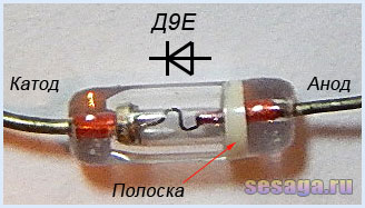
Diodes VD1 – VD4 any from the D9 series. A colored stripe is applied to the diode body on the anode side, identifying the letter of the diode.
As a rectifier assembled on diodes VD5 - VD8, a ready-made miniature diode bridge is used, designed for a voltage of 50V and a current of at least 200 mA.

If you use rectifier diodes instead of a ready-made bridge, you will have to slightly adjust the printed circuit board, or even move the diode bridge outside the main board of the set-top box and assemble it on a separate small board.
For self-assembly of the bridge, the diodes are taken with the same parameters as the factory bridge. Any rectifier diodes from the KD105, KD106, KD208, KD209, KD221, D229, KD204, KD205, 1N4001 - 1N4007 series are also suitable. If you use diodes from the KD209 or 1N4001 - 1N4007 series, then the bridge can be assembled directly from the printed circuit board directly on the contact pads of the board.
LEDs are standard with yellow, red, blue and green colors. Each channel uses 6 pieces:

Transistors VT1 and VT2 from the KT361 series with any letter index.

Transistors VT3, VT4, VT5, VT6 from the KT502 series with any letter index.

Voltage stabilizer type KREN5A with any letter index (imported analogue 7805). If you use nine-volt KREN8A or KREN8G (imported analogue 7809), then resistor R22 is not installed. Instead of a resistor, a jumper is installed on the board, which will connect the middle pin of the microcircuit to the negative bus, or this resistor is not provided at all during the manufacture of the board.

To connect the set-top box to the sound source, a three-pin jack connector is used. The cable is taken from a computer mouse.

Power transformer - ready-made or home-made with a power of at least 5 W with a voltage on the secondary winding of 12 - 15 V with a load current of 200 mA.
In addition to the article, watch the first part of the video, which shows the initial stage of assembling a color music console
This ends the first part.
If you are tempted make color music using LEDs, then select the parts and be sure to check the serviceability of diodes and transistors, for example. And we will carry out the final assembly and configuration of the color and music console.
Good luck!
Literature:
1. I. Andrianov “Attacks for radio receivers.”
2. Radio 1990 No. 8, B. Sergeev “Simple color and music consoles.”
3. Operating manual for the “Start” radio designer.
The inexhaustible potential of LEDs has once again been revealed in the design of new and modernization of existing color and music consoles. 30 years ago, color music, assembled from multi-colored 220-volt light bulbs connected to a cassette recorder, was considered the height of fashion. Now the situation has changed and the function of a tape recorder is now performed by any multimedia device, and instead of incandescent lamps, super-bright LEDs or LED strips are installed.
The advantages of LEDs over light bulbs in color music consoles are undeniable:
- wide color gamut and more saturated light;
- various design options (discrete elements, modules, RGB strips, rulers);
- high response speed;
- low power consumption.
How to make color music using a simple electronic circuit and make LEDs blink from an audio frequency source? What options for converting an audio signal are there? Let's look at these and other questions using specific examples.
The simplest circuit with one LED
First you need to understand a simple color music circuit, assembled on one bipolar transistor, resistor and LED. It can be powered from a DC source with a voltage of 6 to 12 volts. This color music works on one transistor according to the principle of an amplification stage with a common emitter. A disturbing influence in the form of a signal with varying frequency and amplitude arrives at the VT1 base. As soon as the oscillation amplitude exceeds a certain threshold value, the transistor opens and the LED flashes.
The disadvantage of this simplest scheme is that the rate of blinking of the LED depends entirely on the level of the sound signal. In other words, a full-fledged color-musical effect will be observed only at one volume level. Lowering the volume will result in a rare wink, while increasing the volume will result in an almost constant glow.
Scheme with single-color LED strip
The simplest color music above on a transistor can be assembled using an LED strip in the load. To do this, you need to increase the supply voltage to 12V, select a transistor with the highest collector current exceeding the load current and recalculate the resistor value. This simple color music from an LED strip is perfect for beginning radio amateurs to assemble with their own hands, even at home.
Simple three-channel circuit
A three-channel audio converter allows you to get rid of the shortcomings of the previous scheme. The simplest scheme of color music with the division of the sound range into three parts is shown in the figure.  It is powered by a constant voltage of 9V and can illuminate one or two LEDs in each channel. The circuit consists of three independent amplifier stages assembled on KT315 (KT3102) transistors, the load of which includes LEDs of different colors. As a pre-amplification element, you can use a small step-down network transformer.
The input signal is fed to the secondary winding of the transformer, which performs two functions: galvanically isolates the two devices and amplifies the sound from the line output. Next, the signal goes to three parallel-connected filters assembled on the basis of RC circuits. Each of them operates in a specific frequency band, which depends on the values of resistors and capacitors. The low-pass filter passes sound vibrations with a frequency of up to 300 Hz, as indicated by the blinking red LED. Sound in the range of 300-6000 Hz passes through the mid-pass filter, which is manifested in the flickering of the blue LED. The high-pass filter passes a signal whose frequency is greater than 6000 Hz, which corresponds to the green LED. Each filter is equipped with a trimming resistor. With their help, you can set the uniform glow of all LEDs, regardless of the musical genre. At the output of the circuit, all three filtered signals are amplified by transistors.
If the circuit is powered from a low-voltage DC source, then the transformer can be safely replaced with a single-stage transistor amplifier.  Firstly, galvanic isolation loses its practical meaning. Secondly, the transformer is several times inferior to the circuit shown in the figure in terms of weight, size and cost. The circuit of a simple audio amplifier consists of a KT3102 transistor, two capacitors that cut off the DC component, and resistors that provide the transistor with a common emitter. Using a trimmer resistor, you can achieve overall amplification of a weak input signal.
In the case when it is necessary to amplify the signal from the microphone, an electret microphone is connected to the input of the previous circuit, applying potential to it from the power source. The circuit of a two-stage preamplifier is shown in the figure.  In this case, the trimming resistor is located at the output of the first amplifier stage, which gives more opportunities for adjusting sensitivity. Capacitors C1-C3 pass the useful component and cut off the direct current. Any electret microphone is suitable for implementation; for normal operation, a bias of 1.5 V is sufficient.
Color music with RGB LED strip
The following circuit of a color music console operates on 12 volts and can be installed in a car. It combines the main functions of the previously discussed circuit solutions and is capable of operating in color music and lamp modes.
The first mode is achieved through contactless control of the RGB strip using a microphone, and the second mode is achieved through the simultaneous illumination of red, green and blue LEDs at full power. The mode is selected using a switch located on the board. Now let’s take a closer look at how to make color music that is perfect even for installation in a car, and what parts are required for this.
Structural scheme
To understand how this color music console works, let’s first consider its structural diagram. It will help trace the full path of the signal.  The source of the electrical signal is a microphone, which converts sound vibrations from the phonogram. Because This signal is too small and must be amplified using a transistor or operational amplifier. Next comes the automatic level controller (AGC), which keeps the sound fluctuations within reasonable limits and prepares it for further processing. Filters divide the signal into three components, each of which operates only in one frequency range. In the end, all that remains is to amplify the prepared current signal, for which transistors operating in switching mode are used.
Schematic diagram
Based on the structural blocks, we can proceed to a consideration of the circuit diagram. Its general appearance is shown in the figure.  To limit current consumption and stabilize the supply voltage, resistor R12 and capacitor C9 are installed. R1, R2, C1 are set to set the microphone bias voltage. Capacitor C fc is selected individually for a specific microphone model during the setup process. It is needed in order to slightly muffle the signal of the frequency that prevails in the microphone’s operation. Usually the influence of the high-frequency component is reduced.
Unstable voltage in the vehicle network can affect the operation of color music. Therefore, it is most correct to connect homemade electronic devices through a 12V stabilizer.
Sound vibrations in the microphone are converted into an electrical signal and, through C2, are supplied to the direct input of the operational amplifier DA1.1. From its output, the signal goes to the input of the operational amplifier DA1.2, equipped with a feedback circuit. The resistances of resistors R5, R6 and R10, R11 set the gain DA1.1, DA1.2 equal to 11. The elements of the OS circuit: VD1, VD2, C4, C5, R8, R9 and VT1, together with DA1.2, are part of the AGC. At the moment a signal of too large an amplitude appears at the output of DA1.2, transistor VT1 opens and, through C4, closes the input signal to the common wire. This results in an instantaneous reduction in the output voltage.
Then the stabilized alternating current of audio frequency passes through the cut-off capacitor C8, after which it is divided into three RC filters: R13, C10 (LF), R14, C11, C12 (MF), R15, C13 (HF). In order for the color music on LEDs to shine brightly enough, you need to increase the output current to the appropriate value. For tape with a consumption of up to 0.5A per channel, medium-power transistors such as KT817 or imported BD139 without mounting on a radiator are suitable. If the do-it-yourself light-music assembly involves a load of about 1A, then the transistors will require forced cooling.
In the collectors of each output transistor (parallel to the output) there are diodes D6-D8, the cathodes of which are connected to each other and connected to switch SA1 (White light). The second contact of the switch is connected to the common wire (GND). While SA1 is open, the circuit operates in color music mode. When the switch contacts are closed, all the LEDs in the strip light up at full brightness, forming a total white stream of light.
Printed circuit board and assembly parts
To make a printed circuit board, you will need a single-sided PCB measuring 50 by 90 mm and a ready-made .lay file, which can be downloaded. For clarity, the board is shown from the side of the radio elements. Before printing, you must set its mirror image. Layer M1 shows 3 jumpers placed on the parts side.  To assemble color music from an LED strip with your own hands, you will need accessible and inexpensive components. An electret type microphone, suitable in a protective case from old audio equipment. Light music is assembled on a TL072 chip in a DIP8 package. Capacitors, regardless of type, must have a voltage reserve and be designed for 16V or 25V. If necessary, the board design allows you to install output transistors on small radiators. A terminal block with 6 positions is soldered on the edge for supplying power, connecting an RGB LED strip and a switch. A complete list of elements is given in the table.
  In conclusion, I would like to note that the number of output channels in a homemade color music set-top box can be increased as many times as desired. To do this, you need to divide the entire frequency range into a larger number of sectors and recalculate the bandwidth of each RC filter. Connect LEDs of intermediate colors to the outputs of additional amplifiers: violet, turquoise, orange. Do-it-yourself color music will only become more beautiful from such an improvement.
The given diagrams belong to the site cxem.net
Read also
It's hard to find a person who doesn't like listening to music. To satisfy this desire, high-quality music centers, speakers and other devices are purchased. To get even more pleasure, many people think about creating special color effects that can decorate any sound and create a romantic atmosphere on a date or a fun mood when organizing a holiday party. Color music, like music centers, can be purchased, or you can make it yourself. The best option is to make color music using LEDs with your own hands according to one of the proposed schemes.
Advantages of LED products
The modern electronics market presents a wide variety of LED strips that have a wide variety of color effects. With their help, you can create high-quality spot lighting; it is possible to create light music with flashing or blurry effects.
Unlike conventional light bulbs, LEDs have many positive characteristics. Among the main advantages of LED strips are:
- wide and varied range of colors;
- rendering rich colors;
- different design options - rulers, modules, discrete elements, RGB strips;
- high response speed;
- minimum amount of energy consumed.
The ribbons can be used at home, in clubs and cafes, and can be used to effectively illuminate shop windows. This article will describe in more detail the option of LED color music for ordinary home use.
Simple circuit with one lamp
To begin with, it’s worth studying a simple color music scheme. This is a device that consists of one LED, transistor and resistor. Power for such color music can be supplied from a constant current source with a voltage of 6-12 volts. The device operates on the principle of an amplification stage with a common emitter. The impact in the form of a signal varying in frequency and amplitude arrives at the main base. As soon as the oscillation frequency exceeds a certain threshold value, the transistor opens and the LED immediately flashes.

This scheme of simple color music using LEDs has one drawback - the rate of blinking of the LED depends entirely on the level of the sound signal produced. In other words, the light effect will be activated only at a certain level of volume produced by the music center. When the sound intensity decreases, the glow will be constant with occasional winks.
Scheme with one-color ribbon
This color music on a transistor is assembled using an LED strip in the load. To organize such color music, you will need to increase the power supply to 12 V, find and install a transistor with a maximum collector current that exceeds the load current, and you will also need to recalculate the total value of the resistor. This color music is quite simple, made on one single-color LED strip and is ideal for beginner radio amateurs. You can assemble it without any problems at home.
Simple three-channel circuit
To get color music that is free of all the disadvantages listed above, you should use a special three-channel sound converter. Such a circuit is powered from an LED strip with a constant voltage of 9 V and is able to effectively illuminate one or two LEDs in each channel. Among the main structural elements that characterize such a color-musical scheme are:
- three independent amplifier stages, which are assembled using transistors of the KT315 (KT3102) category;
- LEDs of different colors are included in the transistor load;
- For the pre-amplification element, a network small step-down transformer can be used.

The incoming signal is fed to the secondary winding of the transformer, which in turn performs two main functions - it decouples two devices at the galvanic level, and also amplifies the sound from the main linear output. After this, the signal is fed to three parallel and connected filters assembled on the basis of RC circuits. They operate on an individual frequency band, which directly depends on the value of the capacitor and resistor.
Color music with RGB tape
This attachment circuit operates on 12 volts and is ideal for installation on a car. This color music optimally combines the main functions of the previously discussed schemes and is able to work both in the lamp mode and in the color music mode. The second mode is achieved through special non-contact control of the RGB strip via a microphone. As for the lamp mode, it is based on the simultaneous launch of the green, red and blue LED at full power. The mode can be selected using a special switch located on a special board.
To understand how this attachment works, it is worth studying its sequence of actions. The main source of the signal here is a microphone, which converts sound vibrations emanating from the phonogram. The received signal is insignificant and therefore requires amplification. This can be achieved by using a transistor or a special operational amplifier. After this, the automatic AGC level controller starts. It effectively keeps sound fluctuations within reasonable limits and prepares it for subsequent processing. Built-in filters divide the signal into three parts, each of which operates in one specific frequency range. Finally, you just need to amplify the previously prepared current signal. For this purpose, special transistors are used that operate in key mode.

Purchase of a ready-made CMU
If you don’t want to make a color music system for use at home, you can purchase a CMU, that is, a color music installation. This is a ready-made functional solution that includes a controller. It will process the sound, converting it into a light and music visual representation. In the process of reproducing the light, its intensity and color scheme will change, thereby creating the effect of a real disco. The CMU device also includes a panel with built-in diodes.
These devices may be based on a spectral decomposition into frequencies, where each of them will have a specific color scheme or preset adjustments with a variety of effects and their alternation. They can be configured using the included remote control.
Important! Modern CMUs are very simple to install and configure. This is an ideal solution for organizing a home party or disco.
Conclusion
There are quite a lot of schemes for independently performing color music settings. You can choose a fairly simple option, where the color of the RGB tape will simply change, to quite complex ones, which in the process of work will create a large number of different effects, overflows and attenuations. Depending on your skills, you can choose and execute the appropriate option. It is enough to work a little and create something truly unique; it will be lighting equipment that delights with the shimmer of a wide variety of color shades. Also, do not forget that there is always the opportunity to buy a ready-made color music solution and fill your home with color shades and joy.
Structurally, any color and music (light and music) installation consists of three elements. Control unit, power amplification unit and optical output device.
As an output optical device, you can use garlands, you can design it in the form of a screen (classic version) or use electric directional lamps - spotlights, headlights.
That is, any means are suitable that allow you to create a certain set of colorful lighting effects.
The power amplification unit is an amplifier(s) using transistors with thyristor regulators at the output. The voltage and power of the light sources of the output optical device depend on the parameters of the elements used in it.
The control unit controls the intensity of light and the alternation of colors. In complex special installations designed to decorate the stage during various types of shows - circus, theatrical and variety performances, this block is controlled manually.
Accordingly, the participation of at least one, and at most, a group of lighting operators is required.
If the control unit is controlled directly by music and works according to any given program, then the color and music installation is considered automatic.
It is precisely this kind of “color music” that novice designers - radio amateurs - have usually assembled with their own hands over the past 50 years.
The simplest (and most popular) “color music” circuit using KU202N thyristors.

This is the simplest and perhaps the most popular scheme for a color and music console based on thyristors.
Thirty years ago I first saw a full-fledged, working “light music” up close. My classmate put it together with the help of my older brother. It was exactly this scheme. Its undoubted advantage is its simplicity, with a fairly clear separation of the operating modes of all three channels. The lamps do not blink at the same time, the red low-frequency channel blinks steadily in rhythm with the drums, the middle-green channel responds in the range of the human voice, the high-frequency blue reacts to everything else subtle - ringing and squeaking.
There is only one drawback - a 1-2 watt pre-amplifier is required. My friend had to turn his “Electronics” almost “all the way” in order to achieve fairly stable operation of the device. A step-down transformer from a radio point was used as an input transformer. Instead, you can use any small-sized step-down network trans. For example, from 220 to 12 volts. You just need to connect it the other way around - with a low-voltage winding to the amplifier input. Any resistors, with a power of 0.5 watts. Capacitors are also any, instead of KU202N thyristors you can take KU202M.
"Color music" circuit using KU202N thyristors, with active frequency filters and a current amplifier.

The circuit is designed to operate from a linear audio output (the brightness of the lamps does not depend on the volume level).
Let's take a closer look at how it works.
The audio signal is supplied from the linear output to the primary winding of the isolation transformer. From the secondary winding of the transformer, the signal is supplied to active filters, through resistors R1, R2, R3 regulating its level.
Separate adjustment is necessary to configure the high-quality operation of the device by equalizing the brightness level of each of the three channels.

Using filters, signals are divided by frequency into three channels. The first channel carries the lowest frequency component of the signal - the filter cuts off all frequencies above 800 Hz. The filter is adjusted using trimming resistor R9. The values of capacitors C2 and C4 in the diagram are indicated as 1 µF, but as practice has shown, their capacity should be increased to at least 5 µF.

The filter of the second channel is set to medium frequency - from approximately 500 to 2000 Hz. The filter is adjusted using trimming resistor R15. The values of capacitors C5 and C7 in the diagram are indicated as 0.015 μF, but their capacity should be increased to 0.33 - 0.47 μF.

The third, high-frequency channel carries everything above 1500 (up to 5000) Hz. The filter is adjusted using trimming resistor R22. The values of capacitors C8 and C10 in the circuit are indicated as 1000 pF, but their capacitance should be increased to 0.01 μF.

Next, the signals of each channel are individually detected (germanium transistors of the D9 series are used), amplified and fed to the final stage.
The final stage is performed using powerful transistors or thyristors. In this case, these are KU202N thyristors.

Next, there is an optical device, the design and external design of which depends on the imagination of the designer, and the filling (lamps, LEDs) depends on the operating voltage and maximum power of the output stage.
In our case, these are 220V, 60W incandescent lamps (if you install thyristors on radiators - up to 10 pcs per channel).
The order of assembling the circuit.
About the details of the console.
KT315 transistors can be replaced with other silicon n-p-n transistors with a static gain of at least 50. Fixed resistors - MLT-0.5, variable and trimmers - SP-1, SPO-0.5. Capacitors - any type.
Transformer T1 with a ratio of 1:1, so you can use any one with a suitable number of turns. When making it yourself, you can use a Sh10x10 magnetic circuit, and wind the windings with PEV-1 wire 0.1-0.15, 150-300 turns each.
The diode bridge for powering thyristors (220V) is selected based on the expected load power, minimum 2A. If the number of lamps per channel is increased, the current consumption will increase accordingly.
To power transistors (12V), you can use any stabilized power supply designed for an operating current of at least 250 mA (or better, more).
First, each color music channel is assembled separately on a breadboard.
Moreover, the assembly begins with the output stage. Having assembled the output stage, check its functionality by applying a sufficient level signal to its input.
If this cascade works normally, an active filter is assembled. Next, they check again the functionality of what happened.
As a result, after testing we have a really working channel.
In a similar way, it is necessary to collect and rebuild all three channels. Such tediousness guarantees the unconditional functionality of the device after “fine” assembly on the circuit board, if the work is carried out without errors and using “tested” parts.
Possible printed circuit mounting option (for textolite with one-sided foil coating). If you use a larger capacitor in the lowest frequency channel, the distances between the holes and conductors will have to be changed. The use of PCB with double-sided foil may be a more technologically advanced option - it will help get rid of hanging jumper wires.

Use of any materials from this page is permitted provided there is a link to the site