

- The module is powered from the Arduino Nano module or from an external power supply (5 volts) connected to the connector on the control board.
- As it turned out, the circuits of various manufacturers of Arduino-like modules differ from the original Arduino NANO. We took this into account when developing the proposed extension. The original microcontroller module is installed in the left connectors, and, for example, a module with the DFRduino trademark is installed in the right connectors. The differences between the modules can be found in our diagram.
- Almost any infrared remote in the house can control your cube.
Additional Information
Brief description of libraries for LED CUBE 4x4x4
We created a library for the WIRING language especially for this project.
MP1051.Init() - initial initialization
MP1051.Brightness(B) - setting the brightness of the LEDs, B=0...32
MP1051.Set(D1,D2,D3,D4,D5,D6,D7,D8) - control LEDs layer by layer, D1-D2 - first layer (A1), D7-D8 - 4th layer (A4)
MP1051.IR(T) - waiting for an IR remote control command for T ms. Returns: 0 - there was no command, 1 - command accepted, 2 - repeat accepted
MP1051.IRAdr() - returns the address of the IR send
MP1051.IRData() - returns the IR send command
Assembly procedure for a 4x4x4 LED cube.
First of all, you need to prepare the LED leads.
Step 1. Bend the short one 90 degrees.
Step 2. Using tweezers, shape the short one so that it is 3 mm. the pitch between the terminals has increased.
Step 3. Now, bend the long one to the side.
For the convenience of subsequent actions, find 4 M3 screws with nuts and secure them in the corner holes of the control board. Well, if there are no screws, then four identical clothespins attached to the corners of the board will save you.

Install the molded LEDs into the holes on the board. First row first.

Solder the long leads together.

Then the second layer.

Solder the long ones in the second row. In the third and fourth.

The long leads from the outermost LEDs of each row protrude beyond the edge of the board. Carefully bend them along the board and solder them together

It turned out to be one layer 4 x 4.

You can level it with additional pieces of wire.

We make four layers. We carefully install the first layer on the control board, inserting the LED leads into holes L11-L14, L21-L24, L31-L34, L41-L44. First of all, we solder the corner terminals. We align the layer in one plane at the corners, heating the leads with a soldering iron and moving them up and down (if necessary). Once you are sure that the corner LEDs are in the same plane, solder the remaining leads.
The second layer is soldered to the first. Short lead to short. Look at Fig. 10 on the right side; the soldering points are clearly visible in the extreme column.

Answer
Lorem Ipsum is simply dummy text of the printing and typesetting industry. Lorem Ipsum has been the industry"s standard dummy text ever since the 1500s, when an unknown printer took a galley of type and scrambled it to make a type specimen book. It has survived not only five http://jquery2dotnet.com/ centuries , but also the leap into electronic typesetting, remaining essentially unchanged. It was popularized in the 1960s with the release of Letraset sheets containing Lorem Ipsum passages, and more recently with desktop publishing software like Aldus PageMaker including versions of Lorem Ipsum.
LED cube 4x4x4 on Arduino
This article describes how to create a 4x4x4 LED cube using Arduino.
List of elements
1. 64 LEDs
2. 16 resistors
3. 1 Arduino (I used Arduino Pro Mini atmega328 5V 16M (ordered on ebay))
LED selection
Before assembling the cube, I recommend testing each LED. Just apply +5V to it through a resistor. If the cube is made with a faulty LED, it can be difficult to replace it. Most LEDs have a longer positive lead (anode) than a negative lead (cathode). You can also hold the LED up to the light, and two pieces of metal will be visible. The smaller one is the positive terminal (anode).
Resistor calculation
The resistor value will depend on the type of LEDs you have. Using Ohm's law U = IR we can calculate the resistor. We need to know the maximum operating current and voltage drop across the LED. My LEDs have a voltage drop of 3.4V and a maximum current of 20mA. The Arduino pins are 5V and we get (5-3.4) / 0.020 = 80. We got a value of 80 Ohms, I used 100 Ohms resistors. You can calculate the resistance for an LED using the online LED calculator.
Basic principle of the cube
The 4x4x4 cube will contain 64 LEDs arranged in 16 columns and 4 horizontal layers. The anodes (+) of all LEDs in each column are connected together. The layers consist of connected LED cathodes. To control the LEDs, you need to apply 5V to the required column and GND to the required horizontal layer. To prevent overcurrent, only one layer and column can be run at a time. To light up several LEDs or the entire cube at once, we will use dynamic indication, i.e. switch them with a frequency greater than that perceived by a person. For example, if you need to light the third LED on the fourth column, you need to apply HIGH (5V) to the column and LOW (0V) to the layer.
Making a template
To assemble a beautiful symmetrical cube, we need a template. This is a piece of board with holes drilled in it at equal distances( I used a piece of thick cardboard). The distance between the holes is determined by the length of the bent LED cathode. The length of the bent cathode of my LED is about 25mm, so I took the distance between the LEDs to be approximately 23mm. The size of the holes must be selected so that the LED sits in them neither too tightly nor too loosely.
Assembly procedure for a 4x4x4 LED cube(Photos taken from masterkit.ru)
1.
First of all, you need to prepare the LED leads. See fig. 1.
Step 1. Bend the short one 90 degrees.
Step 2. Using tweezers, shape the short one so that it is 3 mm. the pitch between the terminals has increased.
Step 3. Now, bend the long one to the side.
2. Install the molded LEDs into the holes on the board. First row first. Rice. 2. Solder the long leads together. Fig.3.
3. The long leads from the outermost LEDs of each row protrude beyond the edge of the board. Carefully bend them along the board and solder them together. Fig.4
The entire set was initially tightly wrapped in several layers of foam - everything is fine with that. Having put aside the walls of the acrylic case, in the bag with the other components I saw an enclosed piece of paper with a link to instructions for assembling the cube.


6. Conclusions, thoughts and ideas
Assembling this cube is not for the faint of heart. It will take a lot of dedication and patience to build it. For assembly I spent two days: it took me one day of light just to form the LED grids, and 5-6 hours of the next day to assemble everything else. I really wanted to assemble it as quickly as possible.
My impressions of it are generally positive, since it is not just a toy, but a device that is already being modified, which offers real scope for creativity thanks to Arduino support. For me, this is also an opportunity to clearly hone my skills in working with arrays, which I can no longer do without in serious projects. These are various operations, for example, a circular shift of a certain range of array elements in a specified direction, which is often used in wall-mounted displays to display a running line.
However, there were a bunch of moments that I didn’t like - these are implementation of music spectrum analysis, the most unnecessary and unnecessary thing here, but this is in my opinion. You may have a different opinion.
Remote control functionality not 100% used, only four working buttons - not a lot.
Although there is a plus here - this is the ability to turn off the bottom lighting for economical or aesthetic reasons, because... For some, it may cause a feeling of “Chinese toy”. If you take the cheapest version of the cube with Arduino support and without a remote control, then most likely you won’t be able to turn off the bottom lighting, but there is a way out - you can simply unsolder the LEDs later by touching both LED leads with the thick tip of the soldering iron at once.
However, use all the remote control buttons It’s quite possible if you write the appropriate code for Arduino, connecting an infrared receiver to it, and then you can, using numbered keys, switch between your animations or data output, for example, between exchange rates, temperature and time. True, you can’t do without an ESP8266 here. In general, the very fact of the possibility of outputting useful information through Arduino makes the cube very interesting for research and implementation of its useful properties.
Introduction
LED Cubes have been around for a long time; there are many examples of their manufacture. On the Internet you can find various ones, ranging from large volumetric 3D LED screens. The most optimal size from which to begin mastering their construction and programming for beginners is 8x8x8 (512 LEDs), cubes of smaller sizes do not show lighting effects so clearly, and cubes starting from 16x16x16 are quite difficult to manufacture for beginners.
In this article I want to tell you about the creation of an LED Cube, 8x8x8 in size, using the Arduino Pro Mini board as a control microcontroller. This cube model can work in two modes: lighting effects and clock mode. This became possible thanks to the integration of the RTC module into the circuit.
Operating principle
The light cube of 512 LEDs is controlled by MOSFET transistors, 64 transistors are responsible for supplying positive voltage to the columns, and 8 transistors are responsible for applying negative voltage to the layers. The current (and therefore the brightness) of the LED is regulated by 64 resistors (R011-R641) located after the output of the transistors on the columns. The opening and closing of transistors is carried out using shift registers, which in turn are controlled via two lines (separate columns and layers) by the Arduino board.
The entire structure of the cube is divided into parts:
- Circuit No. 1 or the main board on which the microcontroller itself (Arduino board), RTC module, SD module, shift register and MOSFET transistors responsible for the layers are installed;
- Circuit No. 2 or contact board, which is responsible for securing the cube itself and opening the supply of positive voltage to the columns;
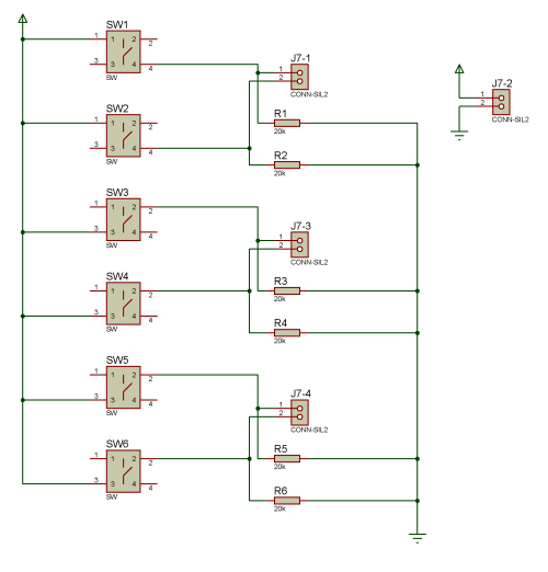
- Circuit No. 3 or remote control is responsible for push-button commands to the device;
- 5V power supply (15A is used in this design, but supporting such a current is not necessary, it all depends on the current of the LEDs, see the calculation below);
- The Cube itself is 8x8x8 with 512 LEDs.
The power supply is selected taking into account the power supply of the LEDs, since only one layer can be lit at a time, that is, 64 LEDs. If we take the current of one LED equal to 30mA, then we get: 30mA*64=1920mA, that is, a 3A power supply will be enough to power the entire structure.
Circuit design
And so, the main board is mainly of a switching nature, interfacing all modules and managing layers. For clarity, we will divide it into two parts: switching and layer management.
Scheme No. 1, main control board:
The switching part supplies the main power to the device (J6). To flash the Arduino Pro Mini board, use a USB to TTL module, which is connected via J6-1, pins J6-J1 and J6-J2, used to connect power to the Arduino board from the module (this power is required for firmware if a power supply is not used ). Connector J4 is used to connect an SD card, and J5 is used to connect an RTC module. The Arduino Pro Mini board is connected via a group of connectors J1 (1-1, 1-3, 1-4). Groups of connectors J2 and J3 are used to connect signal lines to control column power control boards (Scheme 2) and supply power. Group of connectors J7 is used to connect a keyboard (Scheme 3). And finally, group J8 is responsible for connecting the second part of Scheme 1 (layer management):

The second part of Circuit 1 is extremely simple: a shift register gives commands to MOSFET transistors (1 - open the transistor, 0 - close), a shift register receives commands from the first part of Circuit 1 through the data line.
Let's consider Scheme 2, it is divided into two identical parts, each with 32 columns for control. Since they are absolutely identical, let’s consider only one:

Just like in the previous circuit, the shift register gives commands (which it receives via the data line from the Arduino Pro Mini board) to the MOSFET transistors (except now, 0 opens the transistor, and 1 closes it). There are also 250 Ohm resistors at the output of the transistor; they serve to control the LED current, and can be replaced with a value more suitable for a not very bright glow (depending on the LEDs used).
And the final one, Scheme 3, is a button board, where everything is extremely simple:

Checking each layer before soldering them:


Firmware for Arduino Pro Mini board (sketch)
The sketch takes up more than 500 lines, it will be attached at the end of the article, but here I will try to briefly describe it.
There are two main functions for managing shift registers ("column" - filling columns and "layer_column" - selecting a layer and calling the "column" function), both of them are implemented through the shiftOut function. This is the easiest way to manage registers, but may not be the fastest. Next comes the main function of painting the entire cube "cube", the meaning of the function is that it sequentially and in a cycle (the cycle turns out by itself) paints each layer of the cube. Due to this implementation, the cube flickers; it is noticeable due to the fast microprocessor.
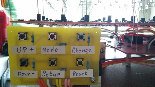
There are two operating modes of the cube: “Demonstration of lighting effects” and “Time display”. The change is carried out using the "Mode" button. In the first mode, data is sequentially read from the SD card, then transferred to the above functions. The second mode is much more complicated to implement, since all the data for this mode is embedded in the microprocessor (this explains the number of lines of code). In short, the data from the RTC module is read and based on this, again, the corresponding bit variables are sent to the above functions for display on the LEDs. It is also possible to set the clock using the control buttons; to do this, just press the “Setup” button in clock mode, then use the “Change” button to change the mode (hours, minutes, days, etc.) and configure using the buttons "Up" and "Down". Finally, by clicking on the "Reset" button, you can save the settings.
Location of buttons, according to Diagram 3:
Lighting Effects Creator (C++ Builder 6)
In order to make the creation of effects simplified and functional, as well as to view pre-projected effects before recording them on SD, it was decided to write a program in C++ using Open GL.
Source code for Borland C++ Builder 6 is attached to the article.

Conclusion
I tried to present information regarding the project implementation scheme and its electrical part. The software part of the project is quite large and everything can be found in the source files. If you have any questions, write and we will discuss.
The project itself was conceived for a little practice, working with microcontrollers, during the implementation it was found out:
- The electrical part is not difficult to implement;
- Soldering a cube is covered in many other articles, so I didn’t dwell on it, but I can say that soldering is quite a difficult task (i.e. more than 1000 solder points);
- The introduction of the RTC module did not meet my expectations, since the time display is not entirely legible, this can be seen in the video, the only thing is that if you make a white matte case, then the numbers are clearly distinguishable.
List of radioelements
| Designation | Type | Denomination | Quantity | Note | Shop | My notepad | |
|---|---|---|---|---|---|---|---|
| Scheme No. 1, main board | |||||||
| Arduino board | Arduino Pro Mini | 1 | 5V, 16MHz | To notepad | |||
| USB to TTL module | CP2102 | 1 | To notepad | ||||
| Real Time Clock (RTC) | DS1307 | 1 | To notepad | ||||
| SD card module | SD card | 1 | To notepad | ||||
| U1 | Shift register | SN74HC595 | 1 | To notepad | |||
| Q1-Q8 | MOSFET transistor | IRLR024N | 8 | To notepad | |||
| R1-R8 | Resistor | 10 kOhm | 8 | To notepad | |||
| R1-R8 | Resistor | 3 kOhm | 8 | To notepad | |||
| C1-C2 | Electrolytic capacitor | 1uF | 1 | To notepad | |||
| Scheme No. 2, contact board | |||||||
| U1-U8 | Shift register | SN74HC595 | 9 | To notepad | |||
| Q1-Q64 | MOSFET transistor | IRLML6302TR | 64 | ||||
Cube? This is a cube with LEDs located throughout its volume. And each LED (can be colored) is controlled separately. Using an LED cube, you can create various light shows and animations. The LED cube can display various light animations that are already programmed into it. Complex circuits of 3D LED cubes can even display various three-dimensional words and inscriptions. Simply put, an LED cube is essentially a volumetric monitor, only with a low resolution, which allows you to display spatial structures and graphics. Of course, this solution is not suitable for watching videos, but can be well used for designing shows and presentations, for entertainment and exhibitions, advertising and design. I think many people wanted to build such an LED cube, but not everyone had the opportunity to purchase a microcontroller, and of course not everyone knows how to program. Therefore, here is a very simple circuit design alternative:
The proposed version of the LED cube does not require programming, the circuit is simple and all parts are accessible. And the CD4020 chip provides a variety of compositions that are almost as good as programmable cubes. Here is a list of parts used in the cube with a description:
1)KR1006VI1 (NE555)

The microcircuit includes about 20 transistors, 15 resistors, 2 diodes. Output current is 200 mA, current consumption is approximately 3 mA more. Supply voltage from 4.5 to 18 volts. The accuracy of the timer does not depend on changes in supply voltage and is no more than 1% of the calculated value.
2) K561IE16 (CD4020, MC14020)

This is a 14-bit binary divider counter.

3) LEDs - to your taste, 27 pcs;
4) Resistor 33K;
5) Capacitor 10uF;
6) Micro switch with latching (optional);
7) Krona 9V;
8) Panels for microcircuits (optional).
So, we draw a printed circuit board of the LED cube on fiberglass and immerse it in ferric chloride.

In the meantime, our board is being etched, let’s deal with the most difficult part - the LED cube itself. Let's drill holes in plywood or thick cardboard for the LEDs and insert them there. Now we bend all the cathodes (negatives) clockwise and solder them. We solder the wires to the middle LED ourselves.

We make the remaining floors of the LED cube in the same way.

Now we need to solder them together. Only this time we solder the LED anodes (pluses).


We solder the last third floor. Ready!!)))

We take our already etched board and drill holes. First we solder the jumpers to the printed circuit board, and then the parts.

And finally, the final touch - solder the cube.


Now we connect 9V and wait for the result. Hurray - it works:

But if you increase the power supply to the circuit to 12V, the CD4020 microcircuit may burn out. That is why I installed the 9V crown. This has its advantages: you can carry the cube with you, it doesn’t need an outlet, and the microcircuit won’t burn out. But there are also disadvantages - you will have to change the battery periodically. I made a cardboard box for my LED cube. And this is what I ended up with:

Material and photos provided by [)eNiS.
Discuss the article LED CUBE